57
The specification and number of AC cables should be selected properly according to on-site
situation. At most 6 cables can be connected. If more than 6 cables are used, please follow
the sequence below to connect them.
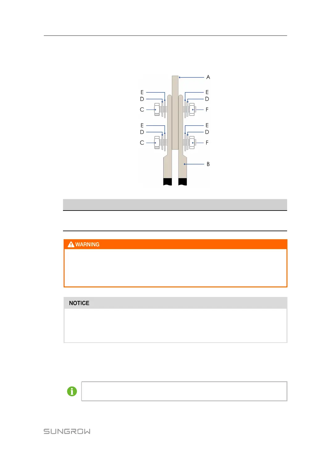
figure 6-13 Connection sequence when two cable lugs are used
A B C D E F
Copper Bus Cable lug Bolt Disc spring
washer
Flat washer Nut
• Incorrect AC connection sequence may cause fire. Please notice the cable con-
nection sequence.
• Ensure the fastness of the connection parts. Poor contact or oxidation of the
contact surface may cause fire.
• Long bolts may affect the insulation and may cause short circuit.
• Remove the heat-shrinkable tubing between the cable lug and the copper bar if
necessary. Poor contact or device damage may follow if otherwise.
step 9 Follow the same procedure in Step 6 to connect cable L2 to the L2, i.e. phase B(V) in the
transformer low-voltage side winding; connect cable L3 to the L3, i. e. phase C (W) in the
transformer low-voltage side winding; leave cable N unconnected.
Yellow, green, and red heat-shrinkable tubings are recommended respectively for
L1, L2, and L3 AC output cables to distinguish the phase.
step 10 Check to make sure the connection is secure.
User Manual 6 Electrical Connection



 To Next Page