4
4
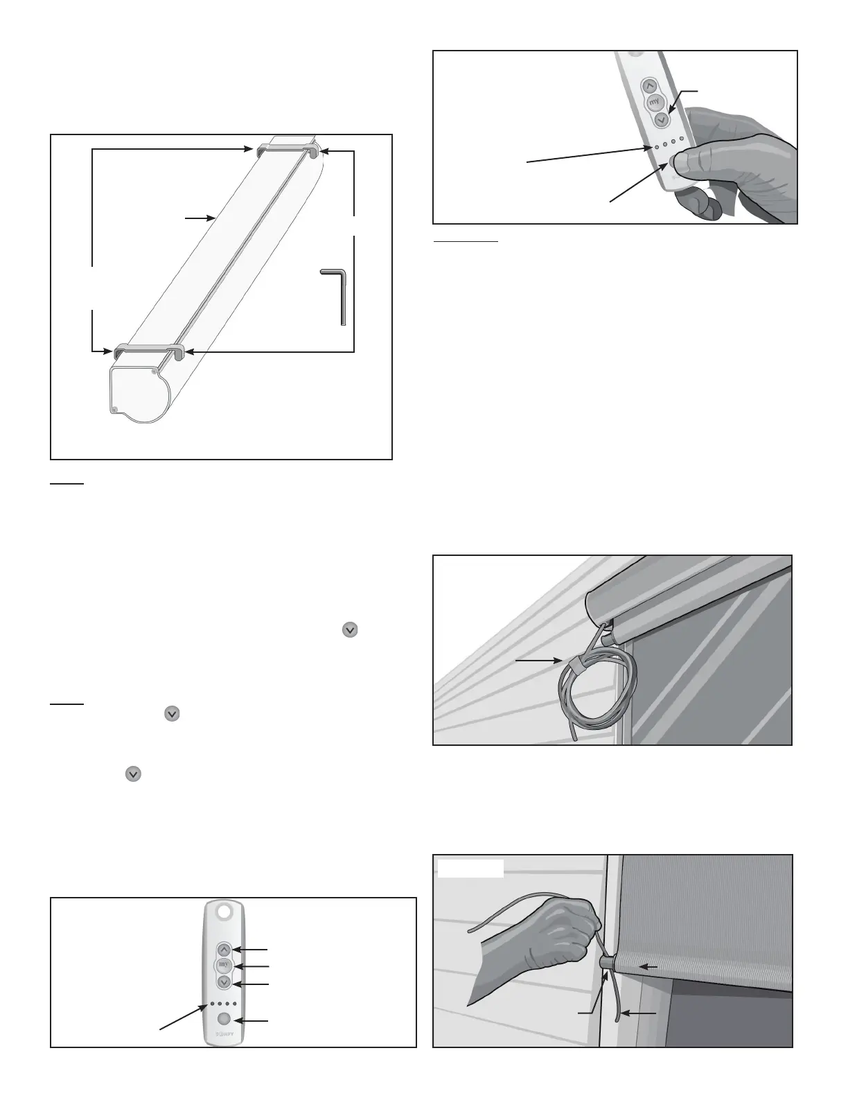
See Figure 6
Note: The Up and Down Stop Limits on the
EasyShade Motor were set at the factory prior to
shipment. The Down Stop Limit was set for a 36
inch extension. This will allow for compleon of the
installaon process.
5
6.DOWN
Figure 7
Note: If the EasyShade does not respond when you
press the DOWN
the DOWN Figure 8
Channel Lights comes on, press the Channel Selector
See Figure 8
7.
8
each end of the Aluminum Housing Assembly, and
See Figure 9
9
end of the Aluminum Housing Assembly, through the
Guide Holes at each end of the Leading Bar, at the
See Figure 10
Figure 9
Vinyl
Coated
Guide
Cable
Figure 8
First Light on the
Use Channel 1
to operate your
EasyShade.
Figure 7
Use Channel 1
Channel Selector
Figure 10
EasyShade
Fabric Panel
Guide Hole Vinyl Coated Cable
Leading Bar
CAUTION: The installaon procedure for the
Motorized EasyShade includes the use of Cable
Guides to stabilize the extended Fabric Panel during
normal use. If your applicaon does not permit the
installaon of the necessary Cable Guides or you
do not plan to install them, you must use addional
care to prevent damage to your product. While
we do not recommend installing the Motorized
EasyShade without the supplied Cable Guides, some
customers may determine that their applicaon
does not have a vercal surface to install the
supplied Cable Guides as instructed.
Figure 6
EasyShade
Assembly
Brackets
Set Screws
Example shown is for the
wrench