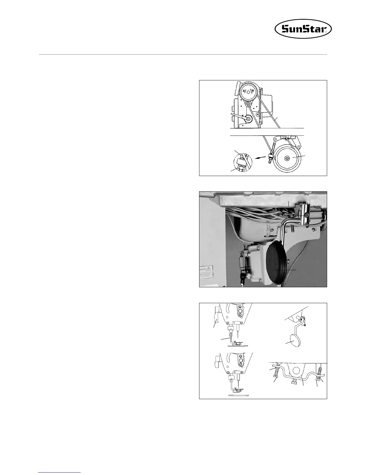
[ Fig. 5 ]
F. After connecting V belt, fully unfasten the fixing nut ①, ②
to up and down, tension occurs to belt by self weight of
motor ③. On this condition, fasten the fixing nut① first
and the fixing nut ② tightly.
[ Fig. 6 ]
A. Insert the presser foot lifter pad (group) ① packed in the
accessory box into control body shaft ② of oil fan.
B. After unfastening the volt ③ and deciding the location
convenient of operation for presser foot lifter, tightly
fasten again.
4) Installation of Presser Foot Lifter Pad
③②
①
[ Fig. 7 ]
A. Put down the feed dog lower than top of the needle plate
by turning the pulley.
B. Put down the presser foot②to presser bar lifter①.
C. Unfasten nut③.
D. Adjust by turning the joint screw ⑥that operation olume
(space) of control body ⑤ should become about 2mm
when lightly press the presser foot lifter pad (group)④ by
hands.
E. After adjustment, joint the nut③tightly.
F. Unfasten the nut⑦.
G. Adjust by rotating joint screw⑧ that joint screw⑧
becomes about 7mm higher than control body⑤.
H. Adjust by turning joint screw⑧ that presser foot②
becomes within 10mm than needle plate when hardly
pressed the presser foot lifter pad (group) ④.
I. After adjustment, joint the nut⑦tightly.
①
②
④
③
⑥
⑤
⑧
⑦
5) Adjustment of Presser Foot Lifter (group) Pad
①
②
④
③
 Loading...