Page | 26
110°C. Subsequently, the inverter will shut down to allow it to cool and reduce its
temperature.
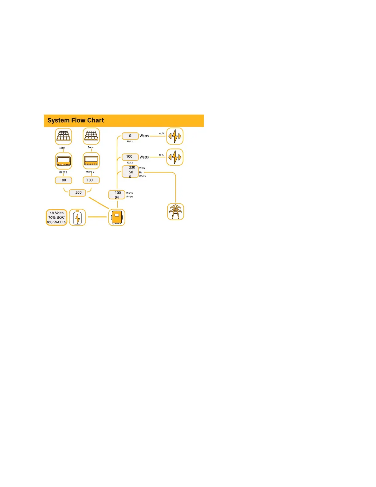
5.5. System Flow Page
Access by clicking on the bar chart on the Home Page.
To better understand the functioning of your system, take a look at the figure bellow:
1. The PV modules charge the batteries.
2. When the batteries reach a specific level (programmable) the battery power is fed into
the inverter.
3. The inverter can then supply power to the grid (export or no export), load, and auxiliary
or smart load.
4. CT coil controls the export power.
What this page displays:
The system flow.
MPPTs power.
Battery status.
Power distribution to load or
grid.