iii
1.0 Introduction ...................................................................................................................1
1.1 About This Manual .................................................................................................1
1.2 Target Audience .....................................................................................................1
1.3 Product Features ...................................................................................................1
1.4 Principles of Water Brake Dynamometer Operation ..............................................2
2.0 Safety Guidelines ..........................................................................................................3
2.1 At Installation .........................................................................................................5
2.2 During Operation ....................................................................................................5
2.3 Lockout/Tagout Procedures ...................................................................................6
3.0 System Overview ..........................................................................................................7
3.1 Overview ................................................................................................................7
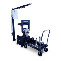
3.2 Dynamometer ........................................................................................................8
SF-902S .................................................................................................................8
3.3 Data Acquisition ...................................................................................................11
Components .........................................................................................................11
The Sensor Box ...................................................................................................11
The Computer System .........................................................................................12
Electrical Requirements .......................................................................................12
Sensor Panel Modules .........................................................................................13
3.4 Accessories and Options .....................................................................................16
4.0 Installation ...................................................................................................................22
4.1 Location ...............................................................................................................22
4.2 Plumbing Diagram ...............................................................................................23
4.3 Unpacking ............................................................................................................24
4.4 Engine Docking Cart ............................................................................................24
4.5 Absorber Stand ....................................................................................................25
4.6 Sensor Box ..........................................................................................................28
4.7 Cooling Towers ....................................................................................................29
4.8 Computer System ................................................................................................31
Communication ....................................................................................................31
Software ...............................................................................................................31
4.9 System Cable Connections ..................................................................................31
Power ...................................................................................................................31
System Interconnect Panel ..................................................................................32
Sensor Interconnect Panel ...................................................................................35
4.10 Expansion Panels ................................................................................................36
Pressure Connections ..........................................................................................36
Thermocouple Connections .................................................................................37
Analog Voltage Expansion ...................................................................................38
4.11 Throttle System ....................................................................................................39
4.12 Initial Check-out ...................................................................................................40
5.0 Operation .....................................................................................................................41
5.1 Introduction ..........................................................................................................41
5.2 Safety ...................................................................................................................41
Emergency Stop ..................................................................................................42
Table of Contents