63
6.3 Calibration
The sensors used with the SF-902S should be periodically calibrated for highest measurement accuracy.
Not all sensor channels require calibration. Some, such as thermocouples, are calibrated at the factory and
normally do not need re-calibration. Pressure transducers and analog voltages, have the calibration set in
the conguration le based on the manufacturer’s specications.
As a rule, the source used to calibrate a sensor should be 10% more accurate than the sensor being
calibrated. For example, if a sensor has an accuracy of +/–1%, the standard used to calibrate it should
have an accuracy of +/–0.1%.
Calibrating the Sensors
NOTE: The following procedures are performed using the WinDyn Data Acquisition and Control Software,
please refer to the software manual for additional calibration details.
Torque:
15. Power on computer system.
16. Power on dyno system.
17. Launch WinDyn application.
18. Use System | Install | Test
Group menu option (or F2
key) to load your specic test
group (.tgp) le.
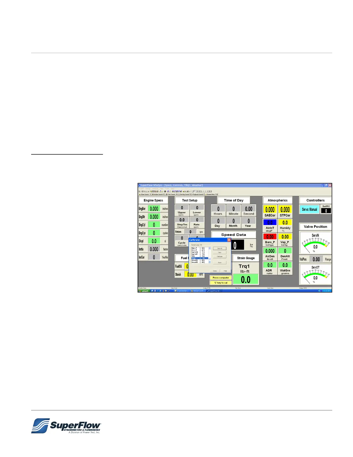
19. Select SCREEN 2 to observe
Trq1 channel (2).
20. Press ‘C’ key on computer
keyboard.
21. Calibration dialog box should
appear on computer screen.
22. Scroll down in channel dialog and highlight ‘Trq1’ channel.
23. Mount cal arm and weight pallet to absorber.
24. Click ‘ZERO’ button.
25. Hang cal weights on weight pallet.
26. Observe ‘Current value = ????’ in Calibrate dialog box.
27. Click ‘Calibrate’ button.
28. Enter computed torque value of hanging weights (Weight x eective length of arm) in calibrate dialog
box. Click OK. The SF-PM system uses a 2 foot arm. The SF-902s and SF-BW use a 3 foot arm.
29. Remove weights and calibration arm
6.0 Maintenance