66
Chassis SC743 User's Manual
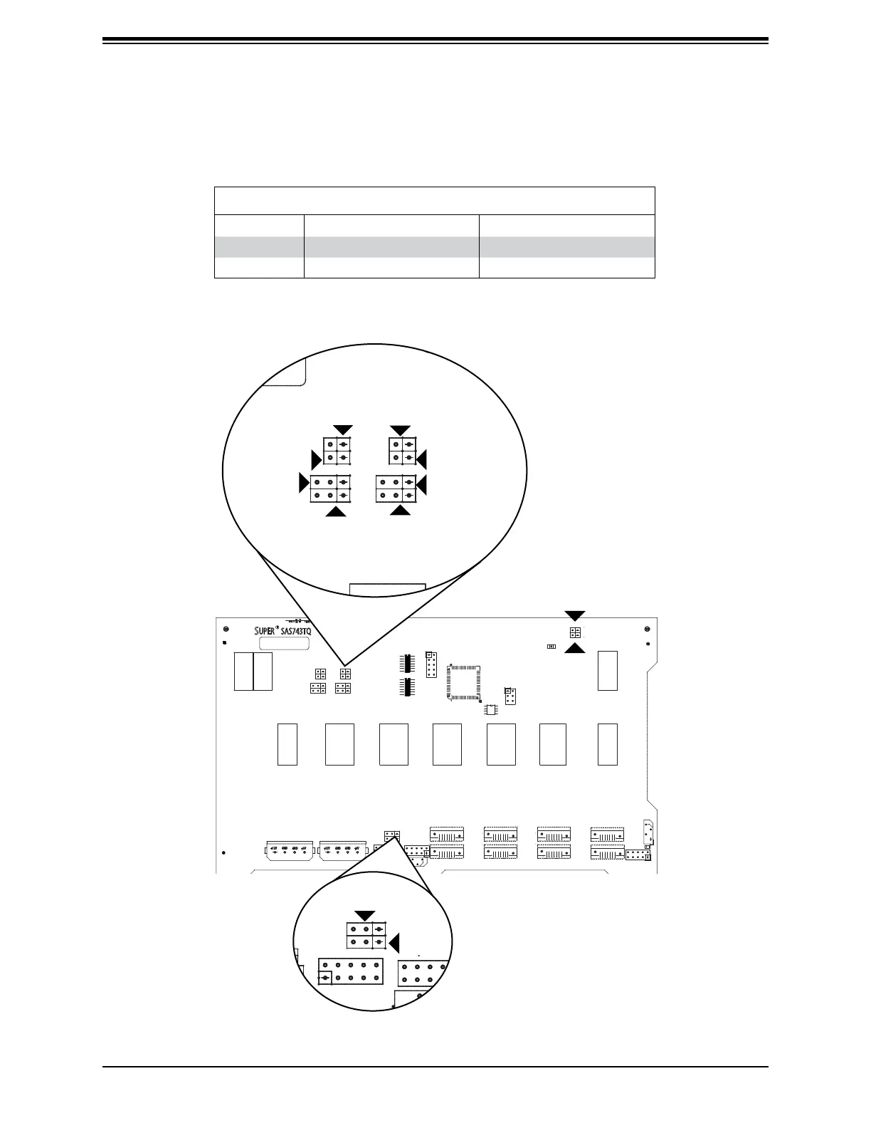
Rear Jumpers and Pin Denitions
Figure C-2. Rear Jumpers
+12V
+12V GND
GND GND GND +5V+5V
48
1
16
64
49
H12
H7
M71
M75
M86
M87
H5
H6
H3
M90
M91
M96
M97
MM2MM3
SAS743TQ
REV 3.00
R
S
UPER
pb
+12V
+12V GND
GND GND GND +5V+5V
48
1
16
64
49
H12
H7
M71
M75
M86
M87
H5
H6
H3
M90
M91
M96
M97
MM2MM3
SAS743TQ
REV 3.00
R
S
UPER
pb
JP50
+12V
+12V GND
GND GND GND +5V+5V
48
1
16
64
49
H12
H7
M71
M75
M86
M87
H5
H6
H3
M90
M91
M96
M97
MM2MM3
SAS743TQ
REV 3.00
R
S
UPER
pb
JP29
JP18
JP42
JP43
JP40
JP33
JP36
JP38
JP41
JP34
JP37
SAS Port Connections in I
2
C and SGPIO Settings
Use the following chart when connecting this backplane. If you connect the SAS ports out of
order, you will not able to easily identify drives using the LED function.
SAS Port Connections in I
2
C and SGPIO Settings
Port # I
2
C SGPIO
# 0 - 3 I
2
C #1 Sideband #1
# 4 - 7 I
2
C #2 Sideband #2
 Loading...