Appendix C: BPN-SAS-743TQ Backplane Specications
67
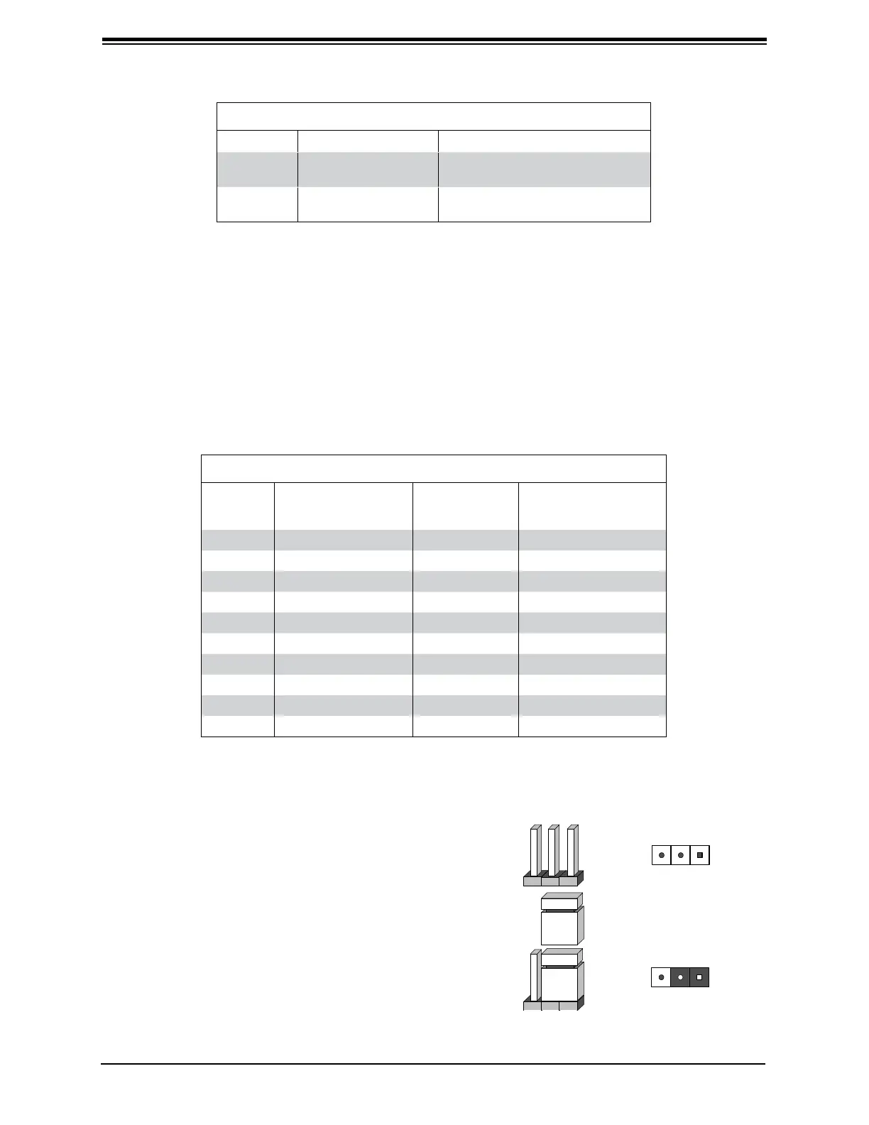
Explanation of Jumpers
To modify the operation of the backplane, jumpers
can be used to choose between optional settings.
Jumpers create shorts between two pins to
change the function of the connector. Pin 1 is
identied with a square solder pad on the printed
circuit board.
Note: On two pin jumpers, "Closed" means the
jumper is on and "Open" means the jumper is off
the pins.
Connector
Pins
Jumper
Setting
3 2 1
3 2 1
Jumper Settings
Jumper Jumper Settings Note
JP18
Open: Enabled
Closed: Disabled
Buzzer reset*
JP29
Open: Default
Closed: Reset
MG9072 chip reset
*The buzzer sound indicates that a condition requiring immediate attention has occurred. The
buzzer alarm is triggered by the following conditions: hard drive failure, fan failure, or system
temperature over 45º Celsius.
I
2
C and SGPIO Mode Jumper Settings
This backplane can utilize I
2
C or SGPIO. I
2
C is the default mode and can be used without
making changes to your jumpers. The following information details which jumpers must be
congured to use SGPIO mode or restore your backplane to I
2
C mode.
I
2
C and SGPIO Settings
Jumper
I
2
C Jumper
Setting (Default)
SGPIO
Jumper
Setting
Note
JP33 Pins 2-3 Pins 1-2 Controller ID #1
JP34 Pins 1-2:ID#0 Pins 1-2 Backplane ID #1
JP36 Pins 2-3 Pins 1-2 Controller ID #2
JP37 Pins 2-3:ID#1 Pins 1-2 Backplane ID #2
JP38 Closed Open I
2
C Reset #2
JP40 Open Closed I
2
C Reset SDOUT #1
JP41 Open Closed I
2
C Reset SDOUT #2
JP42 Pins 2-3 Pins 1-2 Backplane ID SDIN #1
JP43 Pins 2-3 Pins 1-2 Backplane ID SDIN #2
JP50 Closed Open I
2
C Reset #1
 Loading...