Chapter 2: Installation
2-23
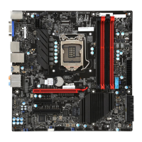
Internal Buzzer (SP1)
The Internal Buzzer (SP1) can be used
to provide audible indications for various
beep codes. See the table on the right
for pin denitions.
A. Internal Buzzer
B. Speaker Header
C. Backup Battery
Internal Buzzer
Pin Denition
Pin# Denitions
Pin 1 Pos. (+) Beep In
Pin 2 Neg. (-) Alarm
Speaker
Speaker (JD1)
On the JD1 header, Pins 3~4 are used
for internal speaker. Close Pins 3~4 with
a cap to use the onboard speaker. If you
wish to use an external speaker, close
Pins 1~4 with a cable. See the table on
the right for pin denitions.
Speaker Connector
Pin Denitions
Pin Setting Denition
Pins 3~4 Internal Speaker
Pins1~4 External Speaker
JTPM1
JIPMB1
S4
I-SATA3
I-SATA0
I-SATA1
JPL1
JPUSB1
JLED1
JVR2
JVR1
JPG1
JPAC1
JBT1
JSTBY1
JSD1
JF1
Rev. 1.00
BIOS
LICENSE
FOR HOME OR OFFICE USE
With FCC Standards
Tested to Comply
JPW2
JL1
JL2
JI2C1
JSPDIF_OUT
JPW1
MAC CODE
BAR CODE
JITP1
LEDM1
SP1
FAN3
FAN2
FAN4
FAN1
FAN5
JD1
JAUDIO1
JBR1
USB8/9(3.0)
OC_FRONT_PANEL
(3.0)
I-SATA0
I-SATA1
I-SATA2
I-SATA3
I-SATA4
I-SATA5
(3.0)
USB 2/3
USB 12/13
FAN1/CPU
PCH_SLOT2 PCI-E 2.0 X4
LAN
HDMI/DP
KB/MOUSE
AUDIO FP
DIMMB1
DIMMB2
HD AUDIO
USB4/5
USB6/7
DIMMA1
DIMMA2
CPU_SLOT1 PCI-E 3.0 X8
CPU_SLOT3 PCI-E 3.0 X16
COM1
VGA(IPMI)
USB 0/1
JI2C2
C7Z97-M
JPME2
JWD1
S8
S11
A
B
System Backup Battery (BT1)
A system backup battery is provided on
the motherboard. This provides backup
power to the CMOS when the system is
off. This is so the motherboard does not
lose its setup conguration. See Chapter
3 for instructions on how to replace the
battery.
C
 Loading...
