Key
Power LED
The Power LED connection is located
on pins 15 and 16 of JF1. Refer to the
table on the right for pin denitions.
NMI Button
The non-maskable interrupt button
header is located on pins 19 and 20
of JF1. Refer to the table on the right
for pin denitions.
NMI Button
PinDenitions(JF1)
Pin# Denition
19 Control
20 Ground
Power LED
PinDenitions(JF1)
Pin# Denition
15 +5V
16 Ground
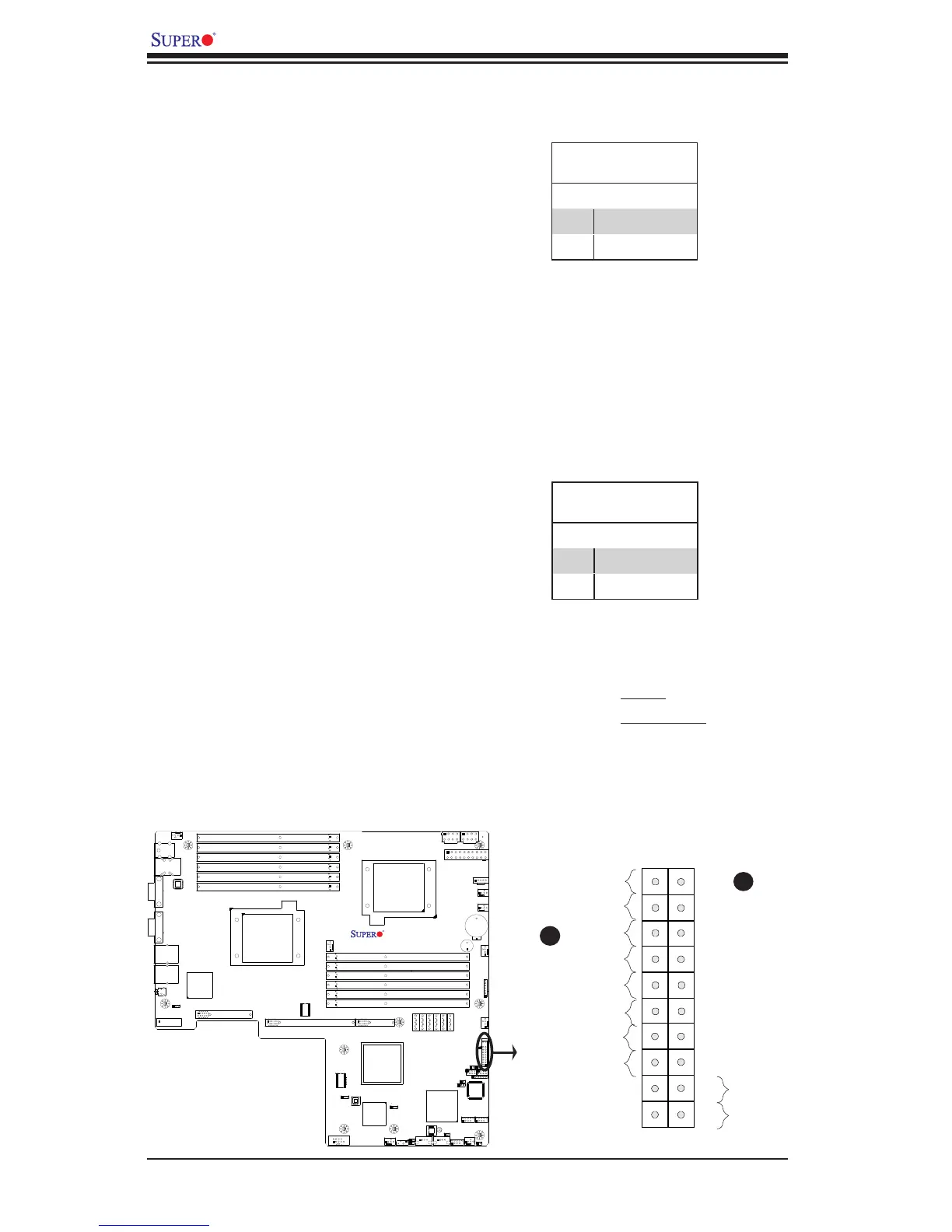
FrontControlPanelPinDenitions
A. NMI
B. PWR LED
A
B
X8DTU/-F
Rev. 2.01

 Loading...


