Chapter 2: Installation
2-33
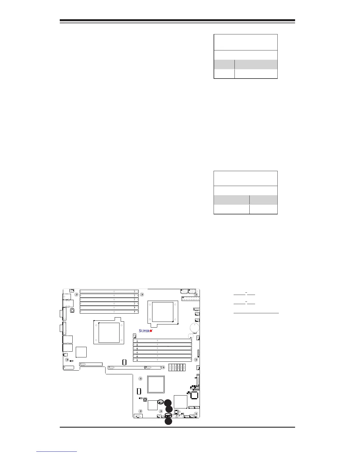
KB/MS
Fan8
(CPU1Fan)
IPMI LAN
USB 0/1
COM1
PHY
VGA
LAN1
LAN2
LAN CTRL
BMC CTRL
BIOS
COM2
USB6
USB7
USB4/5
JTAG Of CPLD
JPI2C
P1-DIMM3A
P1-DIMM3B
P1-DIMM2A
P1-DIMM2B
P1-DIMM1A
P1-DIMM1B
P2-DIMM1B
P2-DIMM1A
P2-DIMM2B
P2-DIMM2A
P2-DIMM3B
P2-DIMM3A
LE2
JUIDB
JPL1
J10
UIOP
SXB2: PCI-E 2.0 x 8
SXB1: PCI-E 2.0 x 16
SXB3: PCI-E 2.0 x 8 in x 4 Slot
J1
J2
J3
JPG1
Fan6
IPMB
JI2C1
JBT1
J13
J14
J12
Fan5
JL1
USB2/3 JLPC1
CPU2
CPU1
Intel 5520
IOH]
Intel ICH10R
South Bridge
T-SGPIO2
T-SGPIO1
J17
JWD
JF1
JOH1
LE1
Fan4
Fan3
SP1
Buzzer
JBAT1
Battery
Fan2
Fan1
JPW1
JPW3
JPW2
JD1
I-SATA5
I-SATA4
I-SATA3
I-SATA2
I-SATA1
I-SATA0
X8DTU/-F
Fan7(CPU2 Fan)
FP CTRL
CPLD
PWRLED/SPK
Rev. 2.01
JPB
JI2C2
JP3
A
A. JI
2
C1
B. JI
2
C2
C. VGA Enabled
B
I
2
C Bus to PCI-Exp. Slots
Jumpers JI
2
C1 and JI
2
C2 allow you to
connect the System Management Bus
(I
2
C) to PCI-Express slots. The default
setting is Open to disable the connec-
tion. See the table on the right for jumper
settings.
I
2
C to PCI-Exp
Jumper Settings
Jumper Denition
Closed Enabled
Open Disabled (Default)
C
VGA Enable/Disable
Jumper Settings (JPG1)
Both Jumpers Denition
Pins 1-2 Enabled
Pins 2-3 Disabled
VGA Enable
JPG1 allows you to enable or disable the
onboard VGA connection. The default
position is on pins 1 and 2 to enable
VGA. See the table on the right for
jumper settings.

 Loading...


