Key
X8DTU/-F
Rev. 2.01
A
B
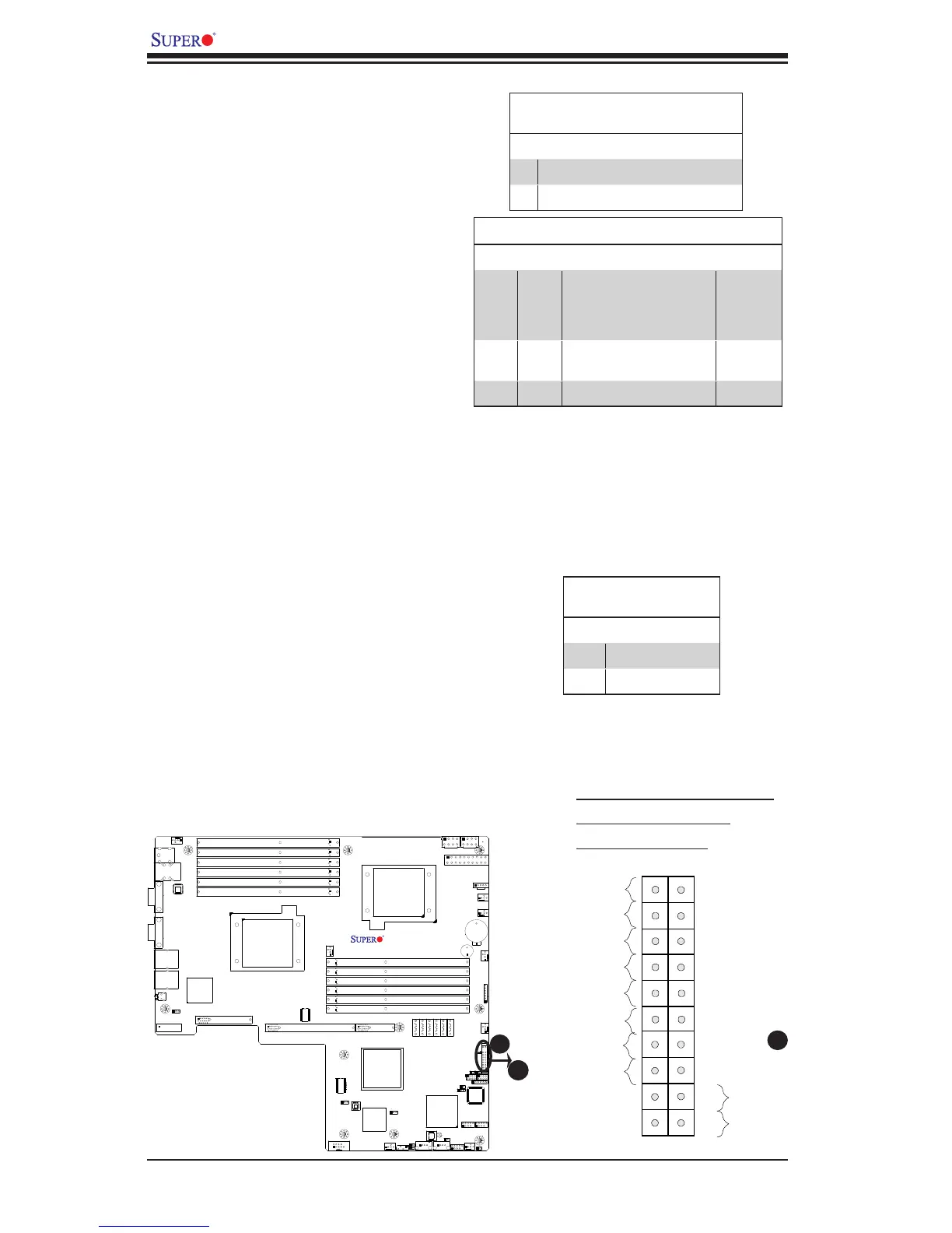
A. OH/Fan Fail/PWR Fail LED
B. Blue LED (UID LED)
C. PWR Supply Fail
Overheat (OH)/Fan Fail/PWR Fail/
UID LED
Connect an LED cable to pins 7 and
8 of JF1 to use the Overheat/Fan
Fail/Power Fail and UID LED connec-
tions. The Red LED on pin 7 provides
warnings of an overheat, fan failure or
power failure. The Blue LED on pin
8 works as the front panel UID LED
indicator. The Red LED takes prece-
dence over the Blue LED by default.
Refer to the table on the right for pin
denitions.
Power Fail LED
The Power Fail LED connection is
located on pins 5 and 6 of JF1. Re-
fer to the table on the right for pin
denitions.
PWR Fail LED
PinDenitions(JF1)
Pin# Denition
5 3.3V
6 PWR Fail LED
C
OH/Fan Fail/ PWR Fail/Blue_UID
LEDPinDenitions(JF1)
Pin# Denition
7 Blue_LED Cathode (UID)
8 OH/Fan Fail/PWR Fail/UID LED
OH/Fan Fail/PWR Fail LED Status
Pin 7 Pin 8 Red LED Blue LED
Low High On: OH/FF/PWR Fail
(Solid On: OH
Fast Blinking: Fan Fail
Slow Blinking: PWR Fail)
Off
High Low Off
(System: Normal)
On
UID LED
High High Off Off

 Loading...


