Key
Power Button
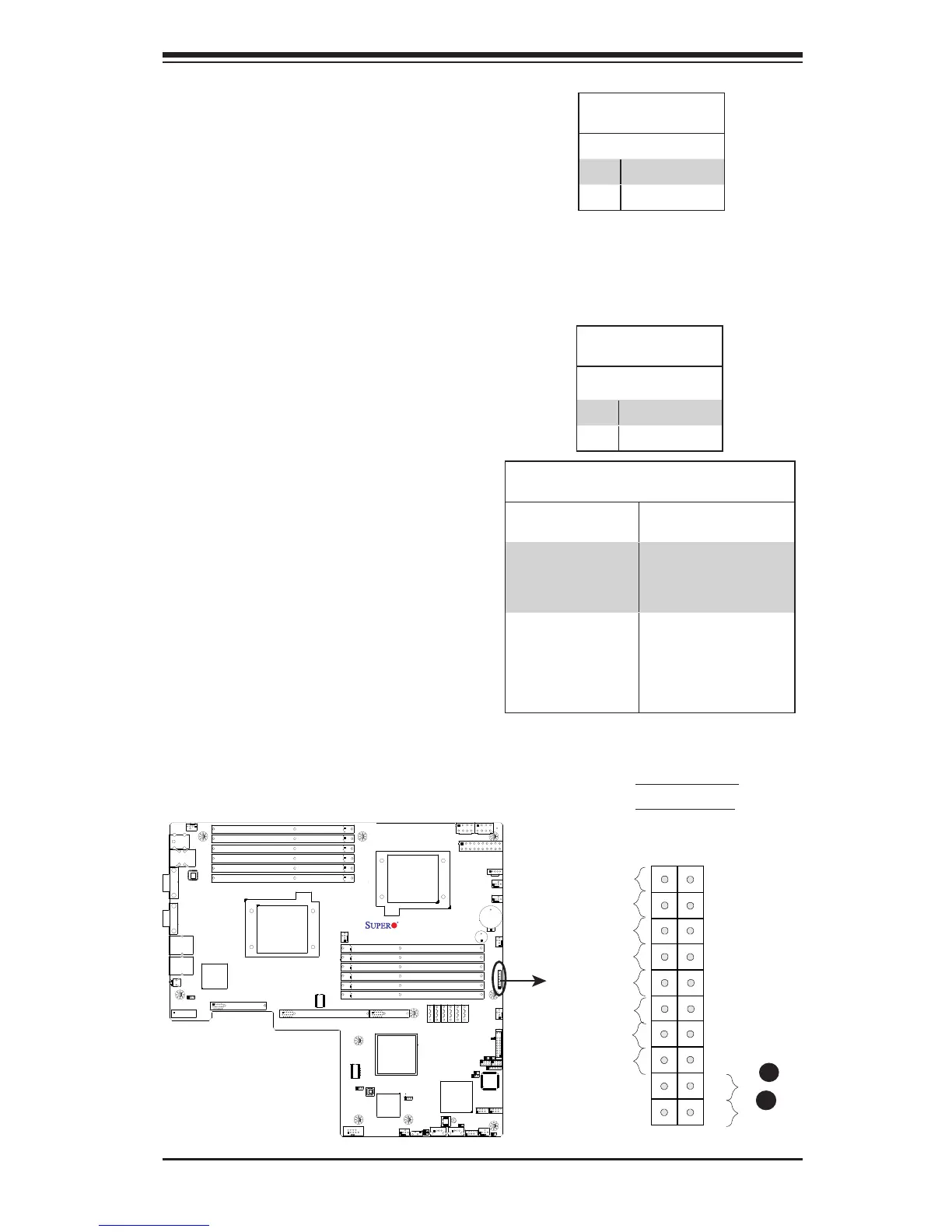
The Power Button connection is located
on pins 1 and 2 of JF1. Momentarily
contacting both pins will power on/off the
system. This button works in conjunction
with the Power-Off setting in the BIOS
Advanced submenu. Refer to the tables
on the right for pin denitions.
Power Button
PinDenitions(JF1)
Pin# Denition
1 Signal
2 +3V Standby
Reset Button
The Reset Button connection is located
on pins 3 and 4 of JF1. Attach it to a
hardware reset switch on the computer
case. Refer to the table on the right for
pin denitions.
Reset Button
PinDenitions(JF1)
Pin# Denition
3 Reset
4 Ground
A. Reset Button
B. PWR Button
A
B
Power Button
Power On/Off Settings
PWR_Off Setting in
the BIOS:
PWR Activity on the
motherboard:
When PWR_Off is
set to Instant_Off
To power-on: Power is
turned on immediately
To pwer-off: PWR is
turned off immediately
When PWR_Off
is set to 4_second
suspend
To power-on: Power is
turned on immediately
To pwer-off: Short both
pins for 4 seconds or
longer to turn off the
power.

 Loading...


