44
Super X11DPG-QT User's Manual
X11DPG-QT
DESIGNED IN USA
REV:1.10A
IPMI CODE
MAC CODE
SAN MAC
BAR CODE
BIOS
LICENSE
CPU1
CPU2
PCH
BMC
LAN
CTRL
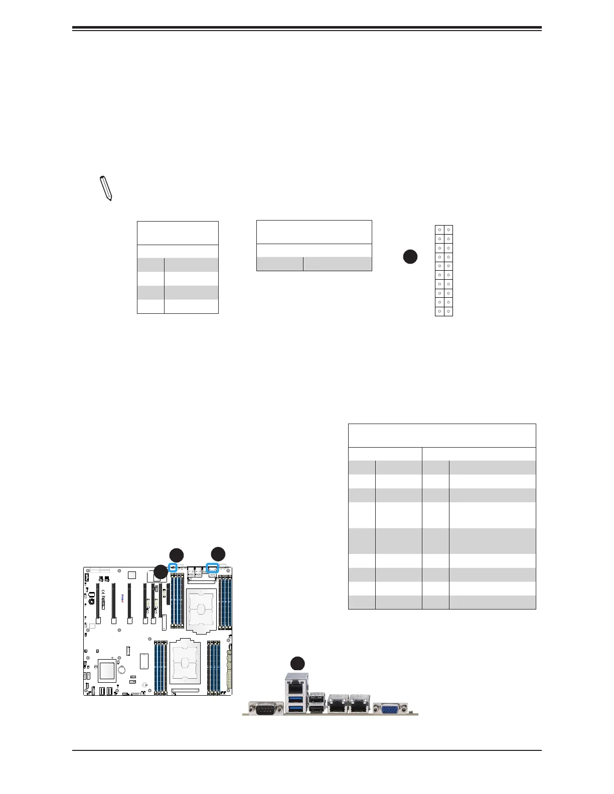
1. UID
2. IPMI_LAN
3. Front UID LED
4. LED2
2
1
2
Unit Identier Switch/UID LED Indicator
A rear Unit Identier (UID) switch (JUIDB1) and an rear LED Indicator (LED2) are located
on the rear side of the system. The front UID LED is located on Pin 7 of the Front Control
Panel (JF1). When you press the UID switch, both front and rear UID LED indicators will be
turned on. Press the UID switch again to turn o the LEDs. The UID Indicators provide easy
identication of a system unit that may be in need of service.
Note: UID can also be triggered via IPMI on the motherboard. For more information
on IPMI, please refer to the IPMI User's Guide posted on our website at http://www.
supermicro.com.
UID Switch
Pin Denitions
Pin# Denition
1 Ground
2 Ground
3 Button In
4 Button In
UID LED
Pin Denitions
Color Status
Blue: On Unit Identied
IPMI LAN Port
An IPMI dedicated LAN that supports Gigabit LAN is located next to USB ports 0/1 on the
back panel. This LAN port is supported by the onboard AST2500 BMC and accepts an RJ45
type cable. Refer to the Section 2.9 for LAN LED information.
UID LED
NIC1 Active LED
HDD LED
PWR LED
3.3V Stby/
UID Button
3.3V Stby
Ground
19
Ground
3.3V Stby
20
1 2
Ground
Power Fail LED
NIC2 Active LED
NMI
3.3V
3.3V
OH/PWR Fail/Fan Fail LED
Power Button
Reset Button
x
x
3
4
LAN Ports
Pin Denitions
Pin# Denition Pin# Denition
1 P2V5SB 10 SGND
2 TD0+ 11 Act LED
3 TD0- 12 P3V3SB
4
TD1+
13
Link 100 LED (Yellow,
+3V3SB)
5
TD1-
14
Link 1000 LED (Yel-
low, +3V3SB)
6 TD2+ 15 Ground
7 TD2- 16 Ground
8 TD3+ 17 Ground
9 TD3- 18 Ground

 Loading...


