Chapter 1: Introduction
1-5
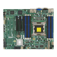
Motherboard Headers/Connectors
Connector Description
I-SAS0~I-SAS3 (SATA 3.0) I-SATA 3.0 ports (supports up to 6Gb/s)
I-SATA0, I-SATA1 (SATA 3.0)
I-SATA2~I-SATA5 (SATA 2.0)
Internal SATA ports (I-SATA0 and I-SATA1 supports up to
6Gb/s), I-SATA2~I-SATA5 supports upo to 3Gb/s)
FAN1~FAN5 Headers for system cooling fans
JSD1 SATA DOM (Disk On Module) Power Connector
JL1 Chassis Intrusion Header
JF1 Front Panel Control Header
JPW1 24-pin Main ATX Power Connector
JPW2 8-pin Secondary Power Connector
JD1 Power LED / Speaker Header (Pins 4~7: External Speaker)
JPI2C1 Power Supply SMBus I2C Header
T-SGPIO1~4 Serial Link General Purpose I/O Headers (5V Gen1/Gen 2)
JTPM1 Trusted Platform Module (TPM) Header
JSTBY1 Legacy Wake On LAN Header
USB0/1, USB2/3 Back panel USB 2.0 ports
USB4/5, USB4/5 Internal USB 2.0 headers
JIPMB System Management Bus Header for the IPMI Slot
JCOM1 Back panel Serial Port Connector
IPMI Back panel IPMI LAN Port
JLAN1/JLAN2 Back panel LAN1 / LAN2 Ethernet Ports
JVGA1 Back panel VGA Port
JOH1 Overheat LED/Fan Fail
BT1 System Battery
SP1 Internal Speaker / Buzzer
SXB1A, SXB1B Slot for Supemicro riser card P/N RSC-R1UW-2E16
SXB2 Slot for Supemicro riser card P/N RSC-R1UW-E8R

 Loading...

