1-10
Supermicro C7X99-OCE/C7X99-OCE-F Motherboard User’s Manual
**Download the AMI status codes at http://www.ami.com/support/doc/ami_aptio_4.x_status_codes_pub.pdf
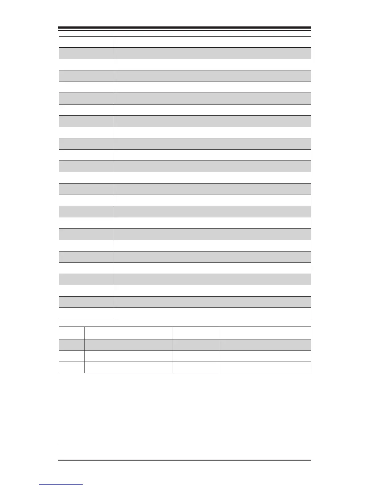
LED Description Color/State Status
LEDM1 BMC Heartbeat* Green: Blinking BMC Normal
LED4 Status Display (C7X99-OCE only) Digital Readout Download the status codes below**
LED1 Power LED On: Steady System On and Running
Connector Description
I/O Back Panel See Back Panel I/O Connectors, below right
Audio FP Front Panel Audio Header
BT1 Onboard Battery
Fan 1,2,3,4,5 System/CPU Fan Headers (Fan1: CPU Fan)
JD1 Speaker/buzzer (Pins 1~4: External Speaker, Pins 3~4: Buzzer)
JF1 Front Panel Control Header
JL1 Chassis Intrusion Header
JPW1 24-pin ATX Main Power Connector (Required)
JPW2 +12V 4-pin CPU power Connector (Required)
JSD1 SATA DOM (Disk On Module) Power Connector
JSTBY1 Standby Power Header
SP1 Internal Speaker/Buzzer
I-SATA0~4, 5~9 (Intel X99) Serial ATA (SATA 3.0) Ports 0~9 (6Gb/sec)
USB 16/17 Front Panel Accessible USB 3.0 Headers 16/17
OC FRONT PANEL Header for the Over-Clocking Control Panel
S4 Power Button
S11 BIOS Restore
S5, S6, S7 Over-Clocking Buttons OC1(15%), OC2(20-25%), OC3 (User-Dened in BIOS)
S9 Home Button, Default setting (non-OC)
S10 Memory Overclocking Button
S8 Clear CMOS Button (on board)
JPI2C1 Power Supply SMBbus I2C Header.
JTPM1 Trusted Platform Module Header
JIPMB1 System Management Bus header (for IPMI only)

 Loading...