Chapter 2: Installation
2-25
MAC CODE
IPMI CODE
BAR CODE
C7X99-OCE-F
SW_BIOSRC
S4
S7
S10
S5
S6
S9
OC_FRONT_PANEL
S8
S11
CLR_CMOS_SW
JUSB30_I2
JAUDIO1
LED4
I-SATA0
I-SATA2
I-SATA4S-SATA0
S-SATA2
AUDIO_FP
JIPMB1
JSD1
MH11
MH2
MH9
MH10
JPW2
CA
LEDM1
JBT1
BT1
+
FAN5
FAN4
FAN1
1
FAN2
4
FAN3
JPL2
JPUSB1
J29
J30
JPME2
JPAC1
JPL1
JI2C1
JI2C2
JPB1
JPG1
JWD1
1
JL2
JL1
JD1
1
JF1
2
19
JPI2C1
JSTBY1
JTPM1
SP1
+
HD AUDIO
VGA
LAN1
LAN2
USB 16/17(3.0)
USB 12/13(3.0)
USB 10/11(3.0)
USB 14/15(3.0)
CPU SLOT6 PCI-E 3.0 X16
PCH SLOT5 PCI-E 2.0 X1 (IN X4)
CPU SLOT4 PCI-E 3.0 X8 (IN X16)
PCH SLOT3 PCI-E 2.0 X1 (IN X4)
CPU SLOT2 PCI-E 3.0 X8 (IN X16)
CPU SLOT1 PCI-E 3.0 X8 (IN X16)
2-3:DISABLE
1-2:ENABLE
:WATCH DOG
SPEAKER
PWR LED
:TPM/PORT80
CPU
CHASSIS INTRUSION
JI2C2
2-3:DISABLE
1-2:ENABLE
JI2C1
PWR ON OH/FF NIC1NIC2RST X
CMOS CLEAR
1-2:NORMAL
2-3:BIOS RECOVERY
JBR1
PWR LEDHDD LED NMIX
2-3:ME MANUFACTURING MODE
JPME2
1-2:NORMAL
1-2 ENABLE
2-3 DISABLE
1-2 ENABLE
2-3 DISABLE
:PWR I2C
1-2 ENABLE
2-3 DISABLE
2-3 DISABLE
1-2 ENABLE
1-2 ENABLE
2-3 DISABLE
JPAC1
VGA
USB14/15 WAKE UP
1-2 RST
2-3 NMI
:SATA DOM POWER
DIMMD2
DIMMD1
DIMMC2
DIMMC1
DIMMB2
DIMMB1
DIMMA2
DIMMA1
JBR1
JWD1
JPW1
JPUSB1
JPB1
JPG1
C
A
LED1
I-SATA1
I-SATA3
I-SATA5S-SATA1
S-SATA3
C7X99-OCE/
COM1
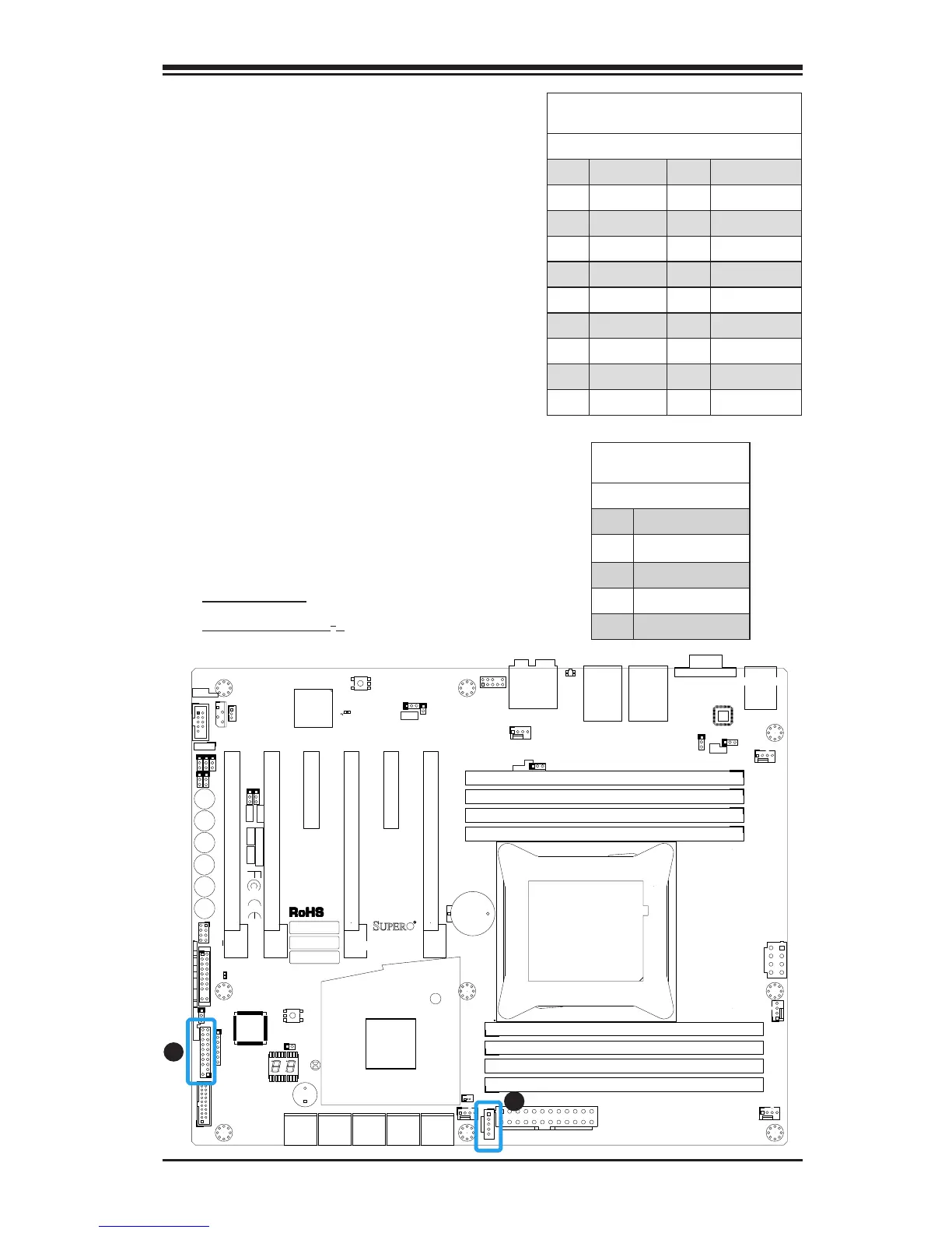
Trusted Platform Module Header
Pin Denitions
Pin # Denition Pin # Denition
1 LCLK 2 GND
3 LFRAME 4 No Pin
5 LRESET 6 VCC5
7 LAD3 8 LAD2
9 VCC3 10 LAD1
11 LAD0 12 GND
13 SMBCLK 14 SMBDAT
15 SB3V 16 SERIRQ
17 GND 18 CLKRUN
19 LPCPD 20 LDRQ1
TPM Header (JTPM1)
This header is used to connect a
Trusted Platform Module (TPM), which
is available from a third-party vendor.
A TPM is a security device that sup-
ports encryption and authentication
in hard drives. It enables the moth-
erboard to deny access if the TPM
associated with the hard drive is not
installed in the system. See the table
on the right for pin denitions.
Power Supply I
2
C (JPI2C1)
The Power Supply I2C Connec-
tor, located at JPI2C, monitors
the status of the power supply,
fan and system temperature.
See the table on the right for pin
denitions.
PWR Supply I2C
Pin Denitions
Pin# Denition
1 Clock
2 Data
3 PWR Fail
4 Ground
5 3.3V
A
B
A. TPM Header
B. Power Supply I
2
C