2-18
Supermicro C7X99-OCE/C7X99-OCE-F Motherboard User’s Manual
C7X99-OCE-F
S11
JUSB30_I2
MH2
1
4
1
1
19
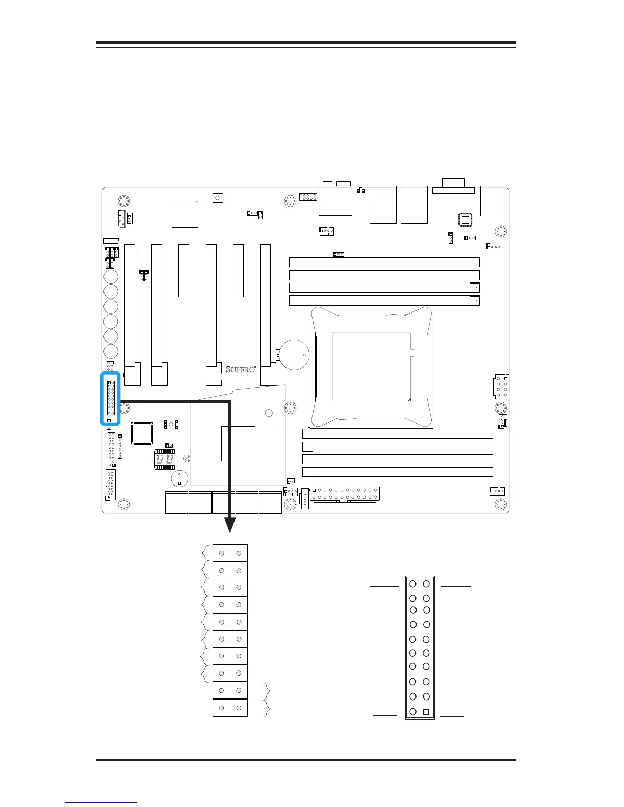
Front Control Panel
JF1 contains header pins for various buttons and indicators that are
normally located on a control panel at the front of the chassis. These
connectors are designed specically for use with Supermicro chassis. See
the gure below for the descriptions of the front control panel buttons
and LED indicators. Refer to the following section for descriptions and
pin denitions.
Pin 19
Pin 20
Pin 1
Pin 2
JF1 Header Pins
Power Button
OH/Fan Fail LED
1
NIC1 LED
Reset Button
2
Power Fail LED
HDD LED
Power LED
#3~4
#1~2
Vcc
Vcc/UID Switch
Vcc
Vcc/Blue UID LED
Ground
Ground
1920
Vcc
X
Ground
NMI
X
Vcc
NIC2 LED