Chapter 2: Installation
2-15
MAC CODE
IPMI CODE
BAR CODE
X10SRA-F
SW_BIOSRC
S4
S8
S11
CLR_CMOS_SW
JUSB30_I2
JAUDIO1
I-SATA0
I-SATA2
I-SATA4S-SATA0
S-SATA2
AUDIO_FP
JIPMB1
JSD1
MH11
MH2
MH9
MH10
JPW2
CA
LEDM1
JBT1
BT1
+
FAN5
FAN4
FAN1
1
FAN2
4
FAN3
JPL2
JPUSB1
J29
J30
JPME2
JPAC1
JPL1
JI2C1
JI2C2
JPB1
JPG1
JWD1
1
JL2
JL1
JD1
1
JF1
2
19
JPI2C1
JSTBY1
JTPM1
SP1
+
HD AUDIO
VGA
LAN1
LAN2
USB 16/17(3.0)
USB 12/13(3.0)
USB 10/11(3.0)
USB 14/15(3.0)
CPU SLOT6 PCI-E 3.0 X16
PCH SLOT5 PCI-E 2.0 X1 (IN X4)
CPU SLOT4 PCI-E 3.0 X8 (IN X16)
PCH SLOT3 PCI-E 2.0 X1 (IN X4)
CPU SLOT2 PCI-E 3.0 X8 (IN X16)
CPU SLOT1 PCI-E 3.0 X8 (IN X16)
2-3:DISABLE
1-2:ENABLE
:WATCH DOG
SPEAKER
PWR LED
:TPM/PORT80
CPU
CHASSIS INTRUSION
JI2C2
2-3:DISABLE
1-2:ENABLE
JI2C1
PWR ON OH/FF NIC1NIC2RST X
CMOS CLEAR
1-2:NORMAL
2-3:BIOS RECOVERY
JBR1
PWR LEDHDD LED NMIX
2-3:ME MANUFACTURING MODE
JPME2
1-2:NORMAL
1-2 ENABLE
2-3 DISABLE
1-2 ENABLE
2-3 DISABLE
:PWR I2C
1-2 ENABLE
2-3 DISABLE
2-3 DISABLE
1-2 ENABLE
1-2 ENABLE
2-3 DISABLE
JPAC1
VGA
USB14/15 WAKE UP
1-2 RST
2-3 NMI
:SATA DOM POWER
DIMMD2
DIMMD1
DIMMC2
DIMMC1
DIMMB2
DIMMB1
DIMMA2
DIMMA1
JBR1
JWD1
JPW1
JPUSB1
JPB1
JPG1
C
A
LE2
I-SATA1
I-SATA3
I-SATA5S-SATA1
S-SATA3
X10SRA/
COM1
LED4
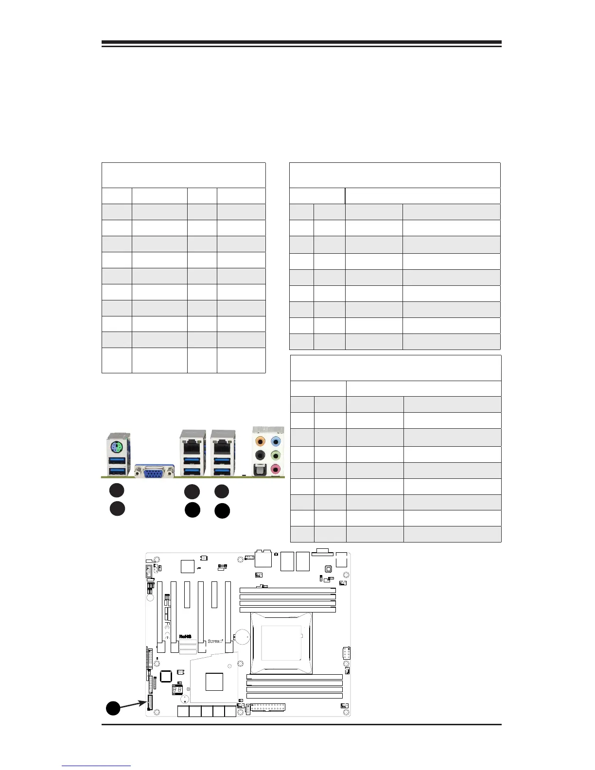
A. Backpanel USB 3.0 #14
B. Backpanel USB 3.0 #15
C. Backpanel USB 3.0 #10
D. Backpanel USB 3.0 #11
E. Backpanel USB 3.0 #12
F. Backpanel USB 3.0 #13
G. USB 3.0 Header #16/17
Universal Serial Bus (USB)
Six USB 3.0 ports (10/11, 12/13, 14/15) are located on the I/O back
panel. In addition, one USB 3.0 header (USB 16/17) is also located on
the motherboard to provide front chassis access using USB cables (not
included). These ports are backward compatible with the USB 2.0 stan-
dard. See the tables below for pin denitions.
A
Front Panel USB (3.0) Header #16/17
Pin Denitions
Pin# Denition Pin# Denition
1 +5V 11 U2DP_B
2 U3RXN_A 12 U2DM_B
3 U3RXP_A 13 Ground
4 Ground 14 U3TXP_B
5 U3TXN_A 15 U3TXN_B
6 U3TXP_A 16 Ground
7 Ground 17 U3RXP_B
8 U2DM_A 18 U3RXN_B
9 U2DP_A 19 +5V
10 USB30_OC
signal
C
E
B
D
G
Back Panel USB (3.0) Ports 10/11, 12/13
Pin Denitions
Pin# Pin# Signal Name Description
1 10 VBUS Power
2 11 D- USB 2.0 Differential Pair
3 12 D+
4 13 Ground Ground of PWR Return
5 14 StdA_SSRX- SuperSpeed Receiver
6 15 StdA_SSRX+ Differential Pair
7 16 GND_DRAIN Ground for Signal Return
8 17 StdA_SSTX- SuperSpeed Transmitter
9 18 StdA_SSTX+ Differential Pair
Back Panel USB (3.0) Ports 14/15
Pin Denitions
Pin# Pin# Signal Name Description
B1 A1 VBUS Power
B2 A2 D- USB 2.0 Differential Pair
B3 A3 D+
B4 A4 Ground Ground of PWR Return
B5 A5 StdA_SSRX- SuperSpeed Receiver
B6 A6 StdA_SSRX+ Differential Pair
B7 A7 GND_DRAIN Ground for Signal Return
B8 A8 StdA_SSTX- SuperSpeed Transmitter
B9 A9 StdA_SSTX+ Differential Pair
 Loading...