Chapter 2: Installation
2-9
1
JD1
7
JIPMB1
C
A
4
5
8
1
JPW2
I-SATA5
I-SATA4
I-SATA3
I-SATA2
2
UID_SW
1
DIMM_C1DIMM_C2DIMM_D1
DIMM_A1
DIMM_B1
DIMM_A2
DIMM_B2
DIMM_D2
I-SATA1
I-SATA0
I-SAS3
I-SAS2
I-SAS1
I-SAS0
7
JVGA
2
1
JF1
19
20
JKBMS1
C
A
UID_LED
JLAN_USB12
X_BT1
+
5
JPI2C1
1
JBT1
1
JPW1
13
JUSB2
3-SGPIO1
2
8
T-SGPIO2 T-SGPIO1
JOH1
1
JL1
1
JI2C2
1
JI2C1
A
DP3
CA
JPBIOS1
JPME1
1
JIBTN1
3
1
3
JWD1
JVR2
3
1
JPL2
1
JPL1
1
3
JVR1
1
3
1
JPUSB1
3
3
JPG1
1
JPB1
1
FANA
FAN5
1
4
FAN3
FAN4
1
FAN2
4
1
FAN1
4
MH11
MH1
MH5
MH9
MH8
MH2
MH10
JCOM1
PCIE6
PCIE5
PCIE4
PCIE3
PCIE7
2
JTPM1
PCIE1
PCIE2
JPK1
1
3
JSD1
JSTBY1
1
3
JLAN1
JLAN2
REV:1.00
Tested to Comply
With FCC Standards
FOR HOME OR OFFICE USE
DESIGNED IN USA
BAR CODE
JCOM2
1
5
6
9
1
7
2
JUSB45
1
7
2
JUSB67
1
7
JUSB89
P1-DIMM2D
P1-DIMM2C
P1-DIMM1C
P1-DIMM1D
P1-DIMM2B
P1-DIMM2A
CPU1
SLOT7 PCI-E 3.0X8 (INX8)
SLOT6 PCI-E 3.0X8 (INX16)
SLOT5 PCI-E 3.0X8 (INX8)
SLOT4 PCI-E 3.0X8 (INX16)
SLOT3 PCI-E 3.0X4 (INX8)
SLOT2 PCI-E 3.0X4 (INX8)
SLOT1 PCI-E 2.0X4 (INX8)
X9SRL
JPK1
JPME1
JBT1 COMS CLEAR
JPBIOS1
JL1 CHASSIS INTRUSION
JSD1:SATA DOM POWER
JPI2C1:PWRI2C
JTPM1:TPM/PORT80
ON:ME RECOVEROS
OFF:NORMAL
COM2
Pin1:RAID_KEY_PCH
Pin3:PCH_DYN_SKU
Pin2:Ground
JPB1
1-2 Enable
2-3 Disable
1-2:NORMAL
2-3:RECOVER BIOS
1-2 Enable
2-3 Disable
JPG1: VGA
OFF:DISABLE
JI2C1/JI2C2
ON: ENABLE
UID
RST
ON
PWR
LAN2
PWR
FF
OH
FAIL
HDD
LED
PWR
X
NIC
1
2
NIC
NMI
LAN1
2-3:NMI
1-2:RST
2-3 Disable
1-2 Enable
JWD1:Watch Dog
JPL1/2: LAN
PWR LED
SPEAKER
1-3:
4-7:
JD1:
VGA
COM1
IPMI_LAN
USB0/1
2-3 ENable
P1-DIMM1B
KB/MOUSE
1-2 Disable
JPUSB1:USB Wake Up
P1-DIMM1A
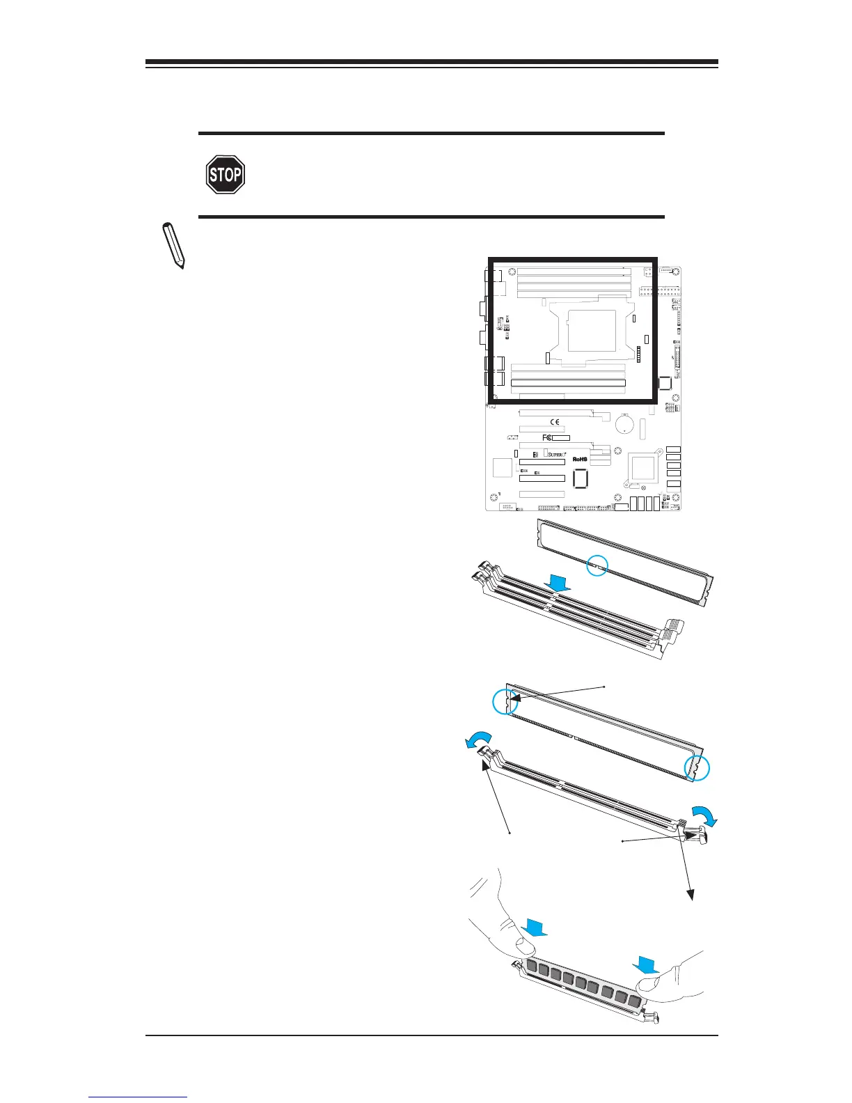
2-3 Installing DDR3 Memory
CAUTION
Exercise extreme care when installing or removing
DIMM modules to prevent any possible damage.
Note: Check the Supermicro website for recommended memory modules.
DIMM Installation
1. Insert the desired number of
DIMMs into the memory slots,
starting with DIMM1A, DIMM(see
the next page for the location). For
best performance, please use the
memory modules of the same type
and speed in the same bank.
2. Push the release tabs outwards
on both ends of the DIMM slot to
unlock it.
Release Tabs
Notches
3. Align the key of the DIMM mod-
ule with the receptive point on the
memory slot.
Press both notches
straight down into
the memory slot.
4. Align the notches on both ends of
the module against the receptive
points on the ends of the slot.
5. Use two thumbs together to press
the notches on both ends of the
module straight down into the slot
until the module snaps into place.
6. Press the release tabs to the lock
positions to secure the DIMM module
into the slot.
Removing Memory Modules
Reverse the steps above to remove the
DIMM modules from the motherboard.