2-20
X9SRL Motherboard Series User’s Manual
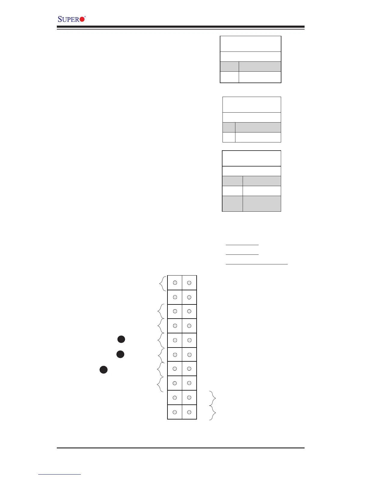
NIC1/NIC2 (LAN1/LAN2)
The NIC (Network Interface Control-
ler) LED connection for LAN port
1 is located on pins 11 and 12 of
JF1, and the LED connection for
LAN Port 2 is on Pins 9 and 10.
NIC1 LED and NIC2 LED are 2-pin
NIC LED headers. Attach NIC LED
cables to NIC1 and NIC2 LED indi-
cators to display network activities.
Refer to the table on the right for
pin denitions.
LAN1/LAN2 LED
Pin Denitions (JF1)
Pin# Denition
9/11 Vcc
10/12 Ground
C
A. NIC1 LED
B. NIC2 LED
C. OH/Fan Fail/UID LED
OH/Fan Fail LED
Pin Denitions (JF1)
Pin# Denition
7 Vcc/Blue UID LED
8 OH/Fan Fail LED
OH/Fan Fail Indicator
Status
State Denition
Off Normal
On Overheat
Flash-
ing
Fan Fail
A
B
Overheat (OH)/Fan Fail/UID LED
Connect an LED cable to the Front
UID and OH/Fan Fail connections
on pins 7 and 8 of JF1 to display
UID (Unit ID) signals or to provide
advanced warnings for chassis over-
heat/fan failure. Refer to the table on
the right for pin de nitions.
Power Button
OH/Fan Fail LED