X
X
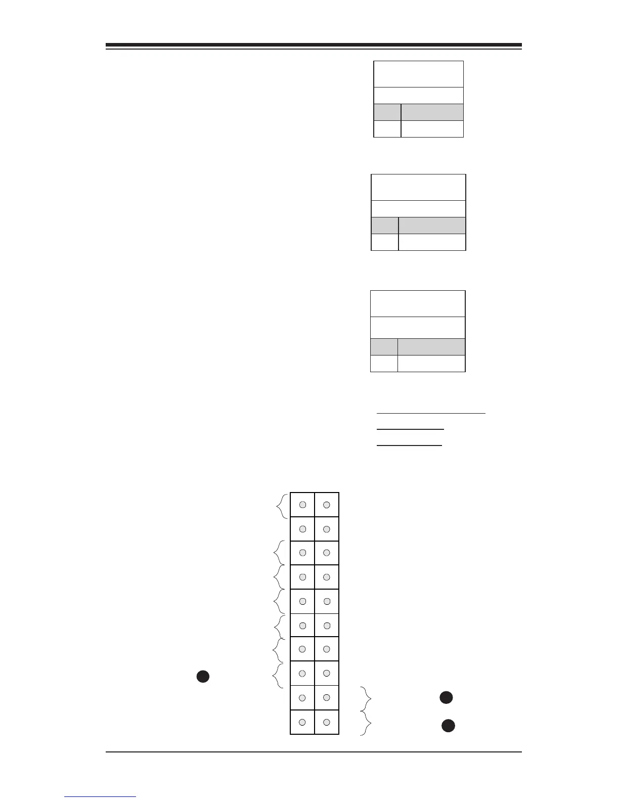
Vcc
NIC2 LED
NMI
Ground
PS Fail LED
Vcc
Power Button
The Power Button connection is
located on pins1 and 2 of JF1. Mo-
mentarily contacting both pins will
power on/off the system. This button
can also be congured to function as
a suspend button (with a setting in
the BIOS - see Chapter 4). To turn
off the power in the suspend mode,
press the button for at least 4 sec-
onds. Refer to the table on the right
for pin denitions.
Power Button
Pin Denitions (JF1)
Pin# Denition
1 Signal
2 +3V Standby
Reset Button
The Reset Button connection is
located on pins 3 and 4 of JF1. At-
tach this to a hardware reset switch
on the computer case to reset the
system. Refer to the table on the
right for pin denitions.
Reset Button
Pin Denitions (JF1)
Pin# Denition
3 Reset
4 Ground
A. Power Supply Fail LED
B. Reset Button
C. PWR Button
A
B
C
Power Supply Fail LED
The Power Fail LED connection
is located on pins 5 and 6 of JF1.
Refer to the table on the right for pin
denitions.
PWR Fail LED
Pin Denitions (JF1)
Pin# Denition
5 Vcc
6 Ground