Chapter 9 Plug-in type electromagnetic flowmeter series
www.supmea.com
50m (please contact the factory for special requirements)
(12) Flowmeter output signal: DC current: 0~10mA, load resistance is 0~1kΩ
4~20mA, load resistance is 0~500Ω
Frequency: 1~5KHz, load resistance is 250~1.2kΩ
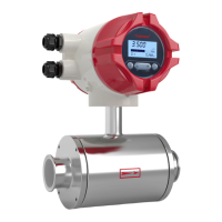
9.4. Structure
The sensor is mainly composed of a measuring head (or measuring tube), an
excitation system, an insertion rod, a junction box, a mounting base, and a bee
positioning mechanism.
Measuring head (or measuring tube): The measuring head (measuring tube) is
located at the particle of the measured flow velocity in the pipeline and is used to
detect the flow velocity at this point. The measuring head (or measuring tube)
consists of an end or conduit made of insulating material, on which a pair of
electrodes is mounted. Except for the electrode tip or the inner wall of the
measuring tube, the other parts are insulated from the fluid to be measured.
Excitation system: The excitation system is used to generate a working magnetic
field. It consists of excitation coil and iron core. It is insulated and sealed into the
insertion rod.
Insertion rod: made of stainless steel material. The east measuring tube of the
measuring head is fixed in the insertion rod. The excitation lead and the electrode
lead are sealed with the medium to be tested by the insertion rod and connected to
the junction box. The insertion rod is welded with a direction indicator rod to ensure
that the working magnetic field, the flow rate and the electrode connection line are
perpendicular to each other during installation, and meet the requirements of
Faraday's law of electromagnetic induction.
Terminal box: The junction box is located on the top of the sensor. The terminals in
the junction box act as a connection between the sensor and the converter.