11
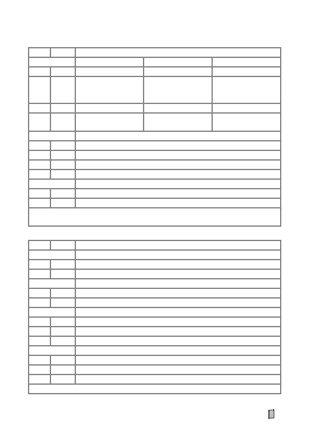
Weighing Signal Input -.
[‘SIG-’ and ‘EXC-’ should
be shorted]
Weighing Signal Input -.
[‘SIG-’ and ‘EXC-’ should
be shorted]
Excitation Voltage +.
[DC5V]
Excitation Voltage +.
[DC12V]
Excitation Voltage +.
[DC12V]
RS232 Digital Communication Port
Signal Ground / Shield Ground.
DC24V[±20%] Power Input Port
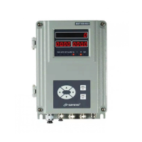
The metal shell should be grounded directly. For separating the controller from the interference of the driving
devices, the DC24V power supply of the controller should not be shared by the DO.
0~20mA Analog Output Port [Definable]
RS485 Digital Communication Port
DO1 Normally Open Contact.
DO1 Normally Closed Contact.
DO2 Normally Open Contact.
DO2 Normally Closed Contact.
Contact Capacity of Relay Switch: AC250V/DC24V, 1A.