3.2.2 Introduction of installation and using
Installation mode1)
Install in the condition of power off;b)
Aim at four installing pores of car, and then use screwdriver to hold;c)
After checking the order of button connection and button plug, plug button switch into d)
instruction plate’s slot;
Connect to the car top board through terminals, and make sure that connection end is e)
instruction plate C
N2’s interface. If connection end is CN1, CTB or instruction plate
can be destroyed.
Definition of terminals’ interface 2)
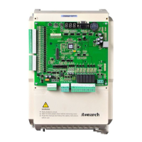
A connection interface that adopts 9PIN parts of an apparatus is in the up and down end a)
of the instruction plate, can communicate with car top board, and make concatenation
with two command boards. The concatenation relationship between car top board and
command board is show
n in Chart9-4:
Fig 3-4 Concatenation sketch between CTB and CCB
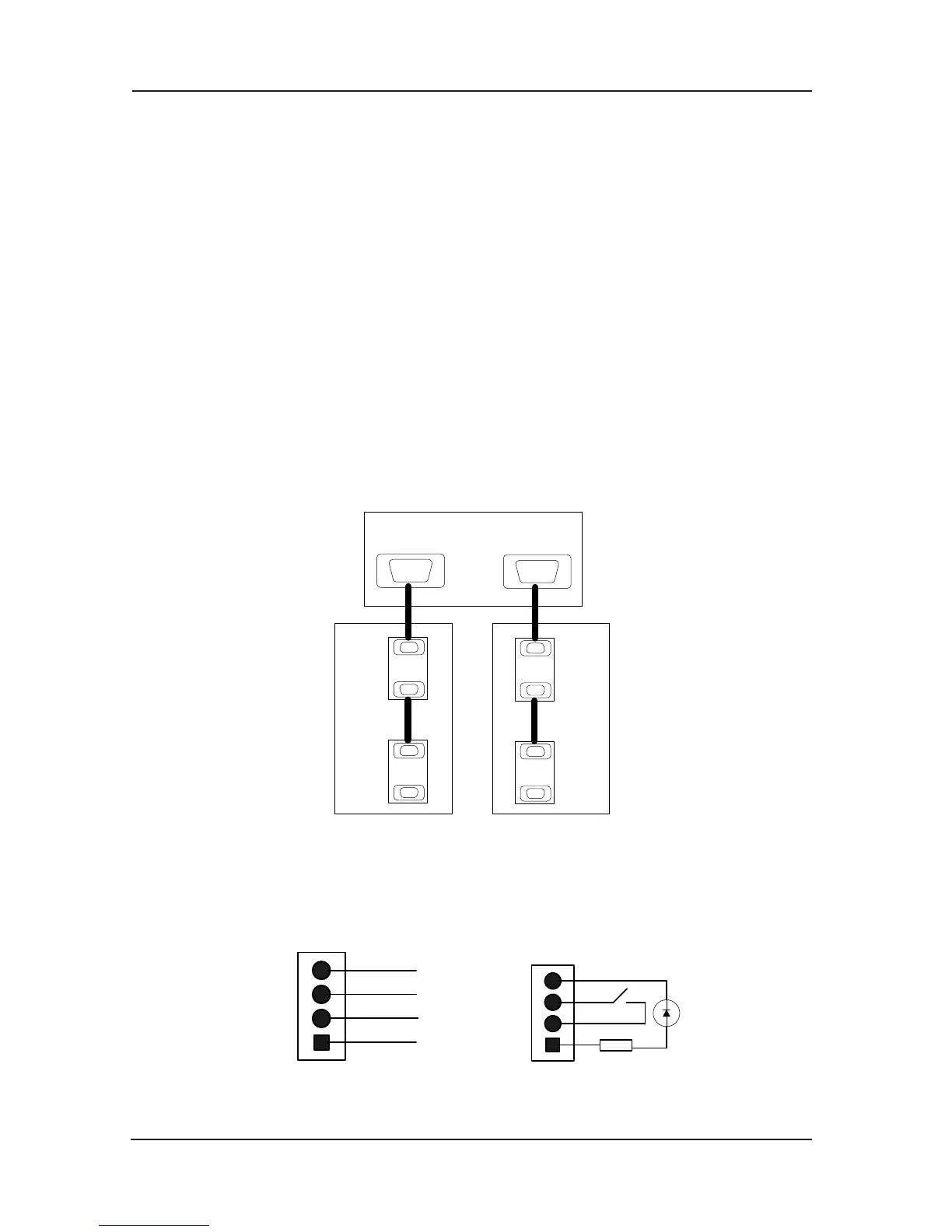
Definition of 4 PIN interfaceb)
Command board’s 4 PIN interface‘s definition of VER-A, VER-B, VER-0 edition is shown in
the following chart 9-5:
 Loading...