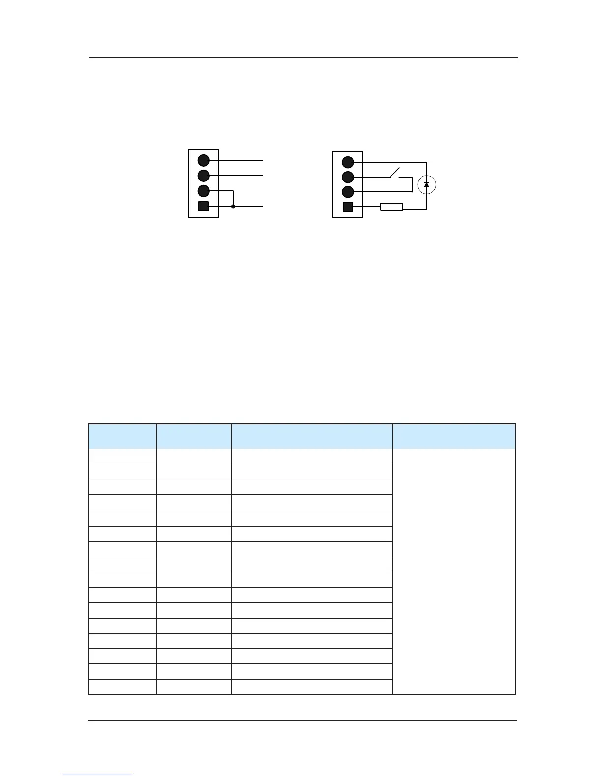
Fig 3-6 Command board’s 4 PIN interface‘s definition and external connection of VER-C
edition
4 PIN interface of VER-C edition has been modified. Getting rid of GND means the avoidance
of the user’s miss-operation to cause the damage of the board due to the short circuit. The
meaning of signals in Chart 9-5 and Chart 9-6: MP24 (24V Power), KEY-IN (Button input
signal), KEY-LED (Button light output),
GND (0V).
Definition of input and output interface 3)
There are 24 instruction inputs, 21 light outputs in each of CCB. When the number of oor is
over 16 and the command board adopts concatenation, the command board 2 only uses input
16 and output 16 (only use for oor input and corresponding light output) .Definition according
to the order is listed as follows :
Command inputa)
Sequence
number(n)
Corresponding
interface
Definition Instruction
1 JP1 Floor 1button input
Input signal corresponds to
oor(16+n) button input for
command board 2
2 JP2 Floor 2 button input
3 JP3 Floor 3 button input
4 JP4 Floor 4 button input
5 JP5 Floor 5 button input
6 JP6 Floor 6 button input
7 JP7 Floor 7 button input
8 JP8 Floor 8 button input
9 JP9 Floor 9 button input
10 JP10 Floor 10 button input
11 JP11 Floor 11 button
input
12 JP12 Floor 12 button input
13 JP13 Floor 13 button input
14 JP14 Floor 14 button input
15 JP15 Floor 15 button input
16 JP16 Floor 16 button input
 Loading...