7-38
REPAIR
7
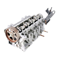
Idler Pulley
Removal and Installation
See Figure 7-88.
Figure 7-88
1. Remove cap screws (1).
Figure 7-89
2. Remove idler pulley (3) and spacer (2).
3. Inspect and replace as needed.
Installation Note
Install idler pulley by reversing the order of removal.
Connecting Rods and Pistons
Removal
See Figure 7-90.
1. Remove cylinder head. (See “Cylinder Head” on
page 7-24.)
2. Remove oil pan. (See “Oil Pan” on page 7-30.)
3. Remove oil pump pickup. (See “Oil Pump Pickup” on
page 7-31.)
4. Remove crankshaft baffle. (See “Crankshaft Baffle”
on page 7-32.)
Figure 7-90
IMPORTANT
Note the placement and orientation of connecting
rods and caps prior to removal.
5. The connecting rods and caps are stamped “2N” (3)
on the intake manifold side of the engine. Mark the
opposite (exhaust) side of connecting rods and caps
1 through 3, starting at the timing chain (front of
engine) moving toward the back.
6. Remove nuts (1) and cap (2).
NOTICE
7. Place rubber hose over connecting rod bolts and
slide connecting rod and piston out the top of the
cylinder block.
TN0721
1
TN0722
3
2
Prevent cylinder bore damage. Place rubber hose
over connecting rod bolts before removing from
cylinder.
Do not drop piston and rod assembly. When the
piston rings are free of the cylinder bore, the
assembly will move freely.
TN0752
2
1
3
 Loading...