1H-2 Ignition System:
Schematic and Routing Diagram
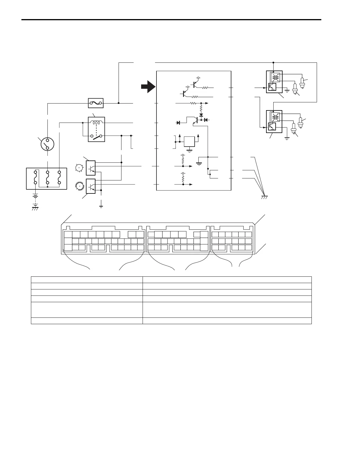
Ignition System Wiring Circuit Diagram
S3RH0A1802001
G04-10
G04-23
12V
5V
5V
G04-6
G04-5
BLK/WHT
BLK/RED
BLK/RED
WHT/BLU
80A
60A 15A
BLK/YEL
BLK/YEL
BRN/WHT
C41-1
C41-2
BLK/ORN
BLK
BLK
C41-3
C41-11
BLK/RED
BLU
YEL/BLK
BLK/ORN
5V
C41-23
1
5
6
2
C41 (31P) G04 (24P) G03 (17P)
123456789
101112131415161718192021
222324252628 27293031
56
1234567
1112
9101113 12141516
1617
12
78
1314
34
910
15
1718
8
192021222324
BLK/WHT
7
3
4
8
9
10
GRN/YEL
GRN/WHT
C41-20
C41-19
5V
5V
12
11
I3RH0A180001-01
1. Ignition switch 7. No.1 spark plug
2. Main relay 8. No.2 spark plug
3. Ignition coil assembly for No.1 and No.4 spark plugs 9. No.3 spark plug
4. Ignition coil assembly for No.2 and No.3 spark plugs 10. No.4 spark plug
5. CMP sensor 11. Sensed information (MAP sensor, ECT sensor, IAT sensor, TP sensor, Knock sensor
(if equipped), VSS, Park/Neutral position signal, Electric load signal, Engine start
signal, Test switch terminal (Vehicle without immobilizer indicator lamp))
6. CKP sensor 12. ECM
 Loading...