5B-27 Manual Transmission/Transaxle:
Input Shaft Disassembly and Assembly
S3RH0A5206019
Disassembly
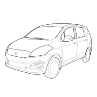
1) Remove input shaft right bearing (2) from input shaft
(1) using bearing puller (3) and press.
2) Drive out 5th gear spacer (2), left bearing (3) and 4th
gear (4) all at once using puller (5) and hydraulic
press.
CAUTION
!
• To avoid gear tooth from being damaged,
support it at flat side of bearing puller.
• Stop press work in the middle way and
take out 5th gear bush to prevent it from
being compressed and then continue to
remove bearing with gear.
3) Take out 4th gear needle bearing and high speed
synchronizer ring.
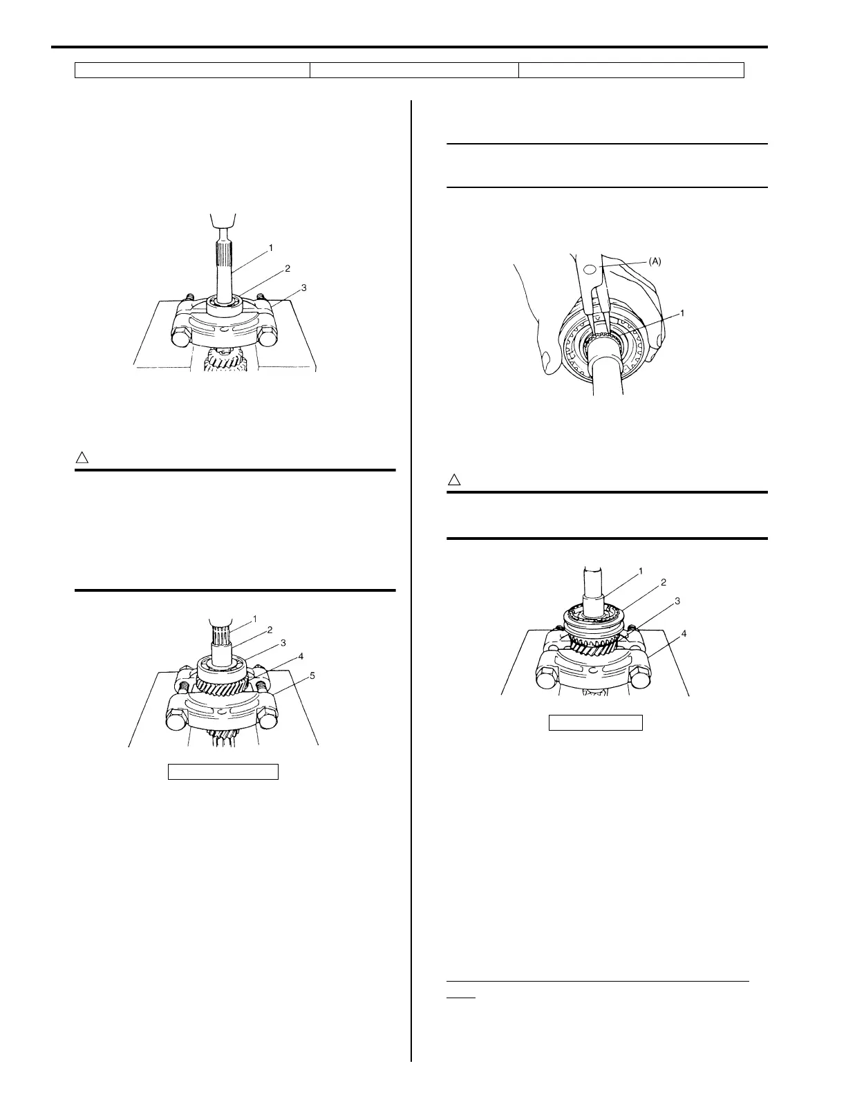
4) Using special tool, remove circlip (1).
NOTE
For smooth removal of circlip, it is
recommended to correct tool tips to be flat.
Special tool
(A): 09900–06107
5) Drive out high speed synchronizer sleeve & hub
assembly (2) together with 3rd gear (3) by using
puller (4) and hydraulic press.
CAUTION
!
To avoid gear tooth from being damaged,
support it at flat side of bearing puller.
6) Take out 3rd gear needle bearing of resin cage type
from input shaft.
7) Disassemble synchronizer sleeve & hub assembly.
Assembly
1) Clean all components thoroughly, inspect them for
any abnormality and replace with new ones as
necessary.
2) If synchronizer parts need to be repaired, check
clearance “a” between ring (2) and gear (1), each
chamfered tooth of gear, ring and sleeve, then
determine parts replacement.
Clearance “a” between synchronizer ring and
gear
Standard: 1.0 – 1.4 mm (0.039 – 0.055 in.)
Service limit: 0.5 mm (0.019 in.)
11. Input shaft 4th gear 22. 2nd gear synchronizer outer ring
1. Input shaft
I4RH01520029-01
I3RH0A520018-01
1. Input shaft
I2RH01520046-01
I2RH01520097-01
 Loading...