7B-65 Air Conditioning System: Automatic Type
DTC B1514 (No.14): Air Flow Control Actuator and/or its Circuit malfunction
S3RH0A7224019
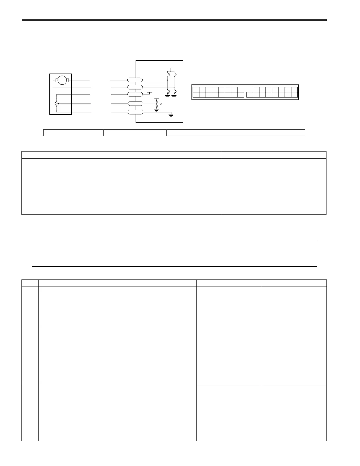
Wiring Diagram
DTC Detecting Condition and Trouble Area
DTC Troubleshooting
NOTE
First, perform “Air flow control actuator motor circuit inspection: Automatic Type”. After that, if DTC
1514 is still detected, perform “Air flow control actuator position sensor circuit inspection: Automatic
Type”.
Air flow control actuator motor circuit inspection
M
12V
5V
5V
RED/WHT
WHT/BLU
BLK/RED
GRY/RED
GRY/BLK
G77-9
G77-12
G77-26
G77-18
G77-17
2
1
3
912
26 1718
I3RH0A722016-01
1. HVAC control module 2. Air flow control actuator 3. HVAC control module connector “G77” (viewed from harness side)
DTC Detecting Condition Trouble Area
• Signal from air flow control position sensor is less than the specified (3.4
V) in operation to FACE direction after 15 seconds.
• Signal from air flow control position sensor is more than the specified (1.6
V) in operation to DEF direction after 15 seconds.
• “GRY/RED”, “GRY/BLK”, “RED/
WHT”, “WHT/BLU” and/or “BLK/
RED” wire faulty
• Linkage faulty
• Heater and cooling unit faulty
• Air flow control actuator faulty
• HVAC control module faulty
Step Action Yes No
1 1) Check if there is any obstruction in operating range of
actuator linkage and if actuator linkage operates
smoothly.
Is there any obstruction? Does actuator linkage operate
smoothly?
Obstruction in operating
range of actuator
linkage, actuator linkage
faulty, and/or internal
fault of heater and
cooling unit.
Go to Step 2.
2 1) Turn ignition switch OFF, and then disconnect air flow
control actuator connector referring to “Air Flow Control
Actuator Removal and Installation in Section 7A”.
2) Turn ignition switch ON, and then check voltage
between “GRY/RED” wire terminal at air flow control
actuator connector and body ground.
Is voltage about 12 V?
Go to Step 5. Go to Step 3.
3 1) Turn ignition switch OFF, and then disconnect HVAC
control module connector referring to “HVAC Control
Module Removal and Installation in Section 7A”.
2) Check resistance between “GRY/RED” wire terminal at
air flow control actuator connector and “GRY/RED” wire
terminal at HVAC control module connector.
Is resistance less than 1 M
Ω
?
Go to Step 4. “GRY/RED” wire open
or high resistance.
 Loading...