Automatic Transmission/Transaxle: 5A-75
TCM Power and Ground Circuit Check
S3RH0A5104039
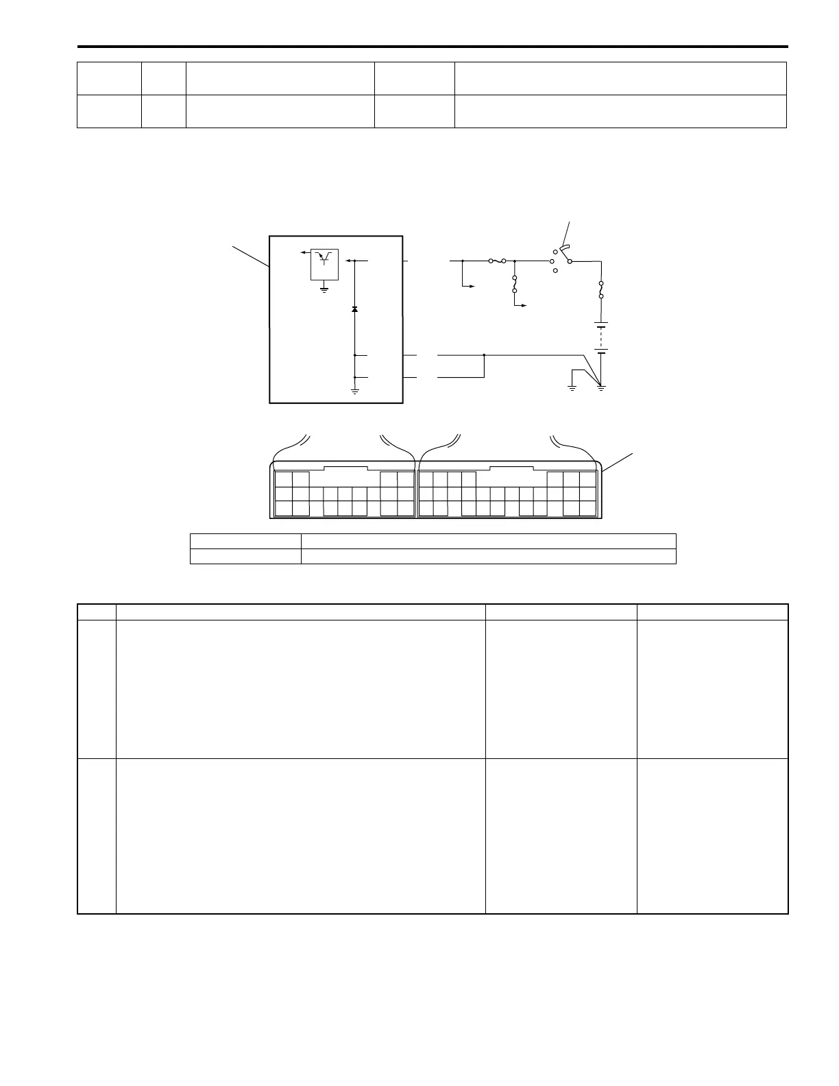
Wiring Diagram
Troubleshooting
20
BLK/
WHT
Power source 10 – 14 V Ignition switch ON
Terminal
Wire
color
Circuit
Standard
voltage
Condition
20 19
15
G08 G07
5V
IG1
3
BLK
BLK
G08-15
G08-19
G08-20
BLK/WHT
1
2
IG11
I2RH0B510034-01
1. TCM 3. Terminal arrangement of TCM connector (viewed from harness side)
2. Ignition switch
Step Action Yes No
1 Check TCM power circuit
1) Disconnect TCM connector with ignition switch OFF.
2) Check for proper connection to TCM at “G08-20”
terminal.
3) If OK, turn ignition switch ON and check voltage at
terminal “G08-20” of disconnected TCM connector.
Is it 10 – 14 V?
Go to Step 2. “BLK/WHT” circuit open.
2 Check TCM ground circuit
1) Turn ignition switch OFF.
2) With TCM connectors disconnected, check for proper
connection to TCM at “G08-15” / “G08-19” terminal.
3) If OK, check resistance between “G08-15” / “G08-19”
terminal of disconnected TCM connector and body
ground.
Is continuity indicated?
TCM power and ground
circuits are in good
condition.
“BLK” circuit for TCM
ground open.
 Loading...