3
Parts listed above are installed respectively into the positions as follows.
Item Part Name Q’ty Remarks
A
Handlebars assembly 1
Handlebar clamp 2
Flange bolt 4 8 × 35 mm
Strap 2 L:120
Fuel tank vent hose 1
Engine stop switch holder 2 Upper and Lower
Screw (with lock washer) 1 3 × 14 mm
Clutch lever cover 1
Clutch adjuster cover 1
B
Radiator cover 2 Right and Left
Flange bolt 6 6 × 12 mm
Stepped washer 6 OD:16.0 ID:6.5 T:3.5
C
Front wheel spacer 2
Front axle nut 1 18 mm
DStand 1
Item Part Name Q’ty Remarks
E
Front fender 1
Flange bolt 4 6 × 16 mm
Collared spacer 4 OD:25.0 ID:6.5 T:6.5
Washer 4 OD:28.0 ID:6.5
F Front wheel assembly 1
G
Spoke nipple wrench 1
Main jet 2
Exchanging parts
Jet needle 1
Exhaust valve stopper tool 1 L:40
H Fuel label 1
I Owner’s service manual 1
OD : Outside diameter (mm)
ID : Inside diameter (mm)
L : Length (mm)
T : Thickness (mm)
T
L
OD
ID
C
B
H
EB
A
D
E
F
C
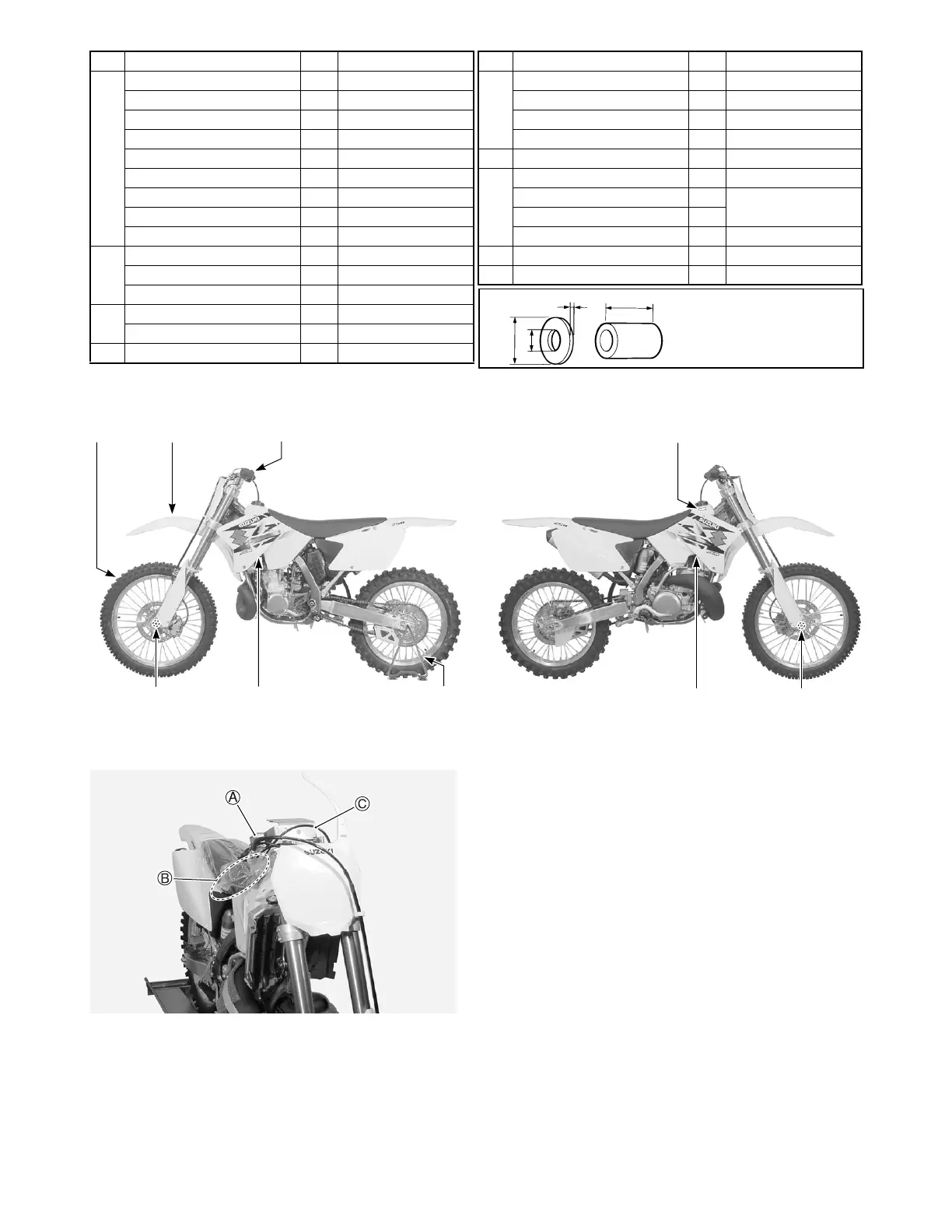
The photograph shown indicates the parts dis-
mounted from the motorcycle in addition to the items
listed above.
A: Front brake master cylinder
B: Throttle assembly
Engine stop switch
C: Clutch cable
 Loading...


