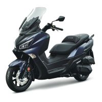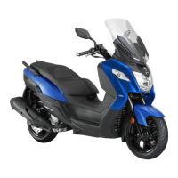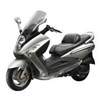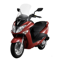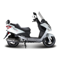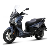
Do you have a question about the Sym JOYMAX 250 and is the answer not in the manual?
| Displacement | 249.4 cc |
|---|---|
| Fuel System | Electronic Fuel Injection |
| Cooling System | Liquid cooled |
| Front Suspension | Telescopic fork |
| Front Brake | Disc |
| Rear Brake | Disc |
| Seat Height | 770 mm |
| Dry Weight | 182 kg |
| Width | 760 mm |
| Height | 1, 420 mm |
| Wheelbase | 1, 550 mm |
| Engine Type | 4-stroke, Single cylinder |
| Transmission | CVT |
| Fuel Capacity | 12 L |
| Length | 2190 mm |
Explains warning, caution, and various service symbols used in the manual.
Outlines essential safety precautions for operating and servicing the vehicle.
Details important guidelines for performing service and maintenance tasks correctly.
General safety and operational guidelines before starting maintenance.
Outlines recommended service intervals for various vehicle components.
Instructions for checking and changing the engine oil, including capacity and type.
Guidelines for safe and effective lubrication system maintenance.
Procedures for removing, disassembling, inspecting, and re-assembling the oil pump.
Safety warnings and handling procedures for fuel system components.
Lists common fuel system issues and their potential causes.
Important safety and procedural notes before engine removal or installation.
Detailed steps for safely removing the engine from the motorcycle frame.
Safety and procedural guidelines for cylinder head and valve servicing.
Common issues related to cylinder head, valve, and camshaft performance.
Safety and handling notes for cylinder and piston servicing.
Detailed steps for removing the cylinder and piston assembly.
General information and specifications for the V-belt drive system.
Common issues and symptoms related to the V-belt drive system.
Safety guidelines for working on the final drive system.
Common problems like motorcycle not moving or unusual noises in the final drive.
Safety notes for alternator and starter motor maintenance.
Inspection and replacement of the starting clutch components.
Detailed steps for disassembling the crankcase.
Procedures for inspecting the crankshaft for run-out and bearing condition.
Safety warnings and general procedures for the cooling system.
Flowchart for diagnosing cooling system issues like overheating.
Sequence for disassembling and assembling body covers, emphasizing care.
Steps for removing and installing the handle cover and related panels.
Common brake system issues like soft lever, uneven, or noisy brakes.
Procedures for removing, installing, and replacing brake pads on the front caliper.
Common problems like hard steering, tilted handlebar, or front cushion issues.
Detailed instructions for removing, installing, and adjusting the steering stem and bearings.
Common issues with rear wheel run-out, soft suspension, and brake noise.
Procedures for removing and installing the rear suspension shock absorbers.
Troubleshooting guide for common electrical system problems.
Procedures for removing, checking voltage, and charging the battery.
Inspection and testing of ignition coil and pulse generator.
Steps for connecting diagnostic tools and checking ECU parameters and codes.
Steps for checking PM sensor voltage using a multimeter.
Steps for checking TPS working voltage and output voltage with a multimeter.
Method for measuring TW sensor resistance at different temperatures.
Steps for checking O2 Sensor heater voltage and electrical resistance.
Steps for confirming fuel pump working voltage and liquid-level gauge function.
Steps for measuring fuel injector resistance and observing spray pattern.
Method for measuring the resistance value of the pulse sensor.
Overview of check light errors and general countermeasures.
Manual procedure for clearing trouble codes from the ECU.
