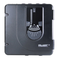
Do you have a question about the System Sensor FAAST LT and is the answer not in the manual?
| Type | Aspirating Smoke Detector |
|---|---|
| Technology | Laser-based detection |
| Detection Principle | Light scattering |
| Operating Voltage | 24 VDC |
| Sensitivity | Adjustable |
| Temperature Range | 32°F to 120°F (0°C to 49°C) |
| Humidity Range | 10% to 93% RH, non-condensing |
| Approvals | UL, FM |
| Communication | Modbus protocol |
| Relay Outputs | 2 relay outputs |
Details the operational states of the FAAST LT device.
Provides an overview of the PipeIQ software application.
Explains the graphical elements of the PipeIQ interface.
Guides users on establishing a USB connection for configuration.
Steps to prepare for connecting the FAAST LT device to a PC.
How to check device information and event logs.
Crucial information before modifying FAAST LT parameters.
Process to download configuration settings to the device.
Instructions for adjusting the device's internal clock.
How to configure the sensitivity for alarm detection.
Covers creating projects and defining pipe layouts.
Details report types and how to use the PipelQ help system.
Lists all configurable parameters and their specifications.
Default settings for stand-alone FAAST LT units.
Configuration for channels, fan speed, and flow limits.
Settings for fault reporting delays and filter maintenance.
Configuration for auxiliary relays and external input functions.
Covers pre-alarm delays and day/night mode.
Configuration for day/night alarm levels and alarm modes.
Settings for sensor communication timeouts and output behavior.
Lists default values for stand-alone units across parameters.
Continues the list of default parameter values for stand-alone units.
Lists default values for loop-based units across parameters.
Continues the list of default parameter values for loop-based units.
Details faults related to configuration, EEPROM, and communication.
Lists faults associated with flow, fan, and sensor issues.
Covers alerts for temperature, power, and filter status.
Details alerts for sensor compensation and PCB errors.
Example pipe configuration for a 1-channel Class C setup.
Example pipe configuration for a 1-channel Class B setup.
Example pipe configuration for a 1-channel Class A setup.
Example of a 1-channel pipe with a branch.
Example for a 1-channel Class C pipe with an external filter.
Example for a 1-channel Class B pipe with an external filter.




 Loading...