114 PDRP-2001 Series Manual — P/N 53043:E4 7/28/2016
NFPA Standard-Specific Requirements NFPA 72 Auxiliary Fire Alarm System
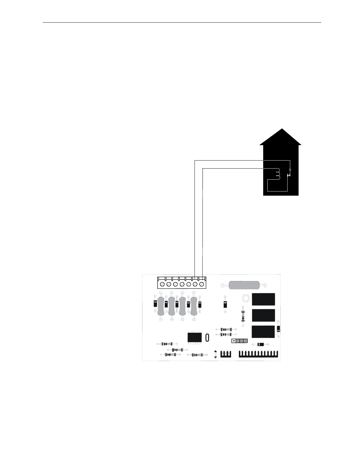
C.1 NFPA 72 Auxiliary Fire Alarm System
All connections are power-limited and supervised. This application is not suitable for separate
transmission of sprinkler supervisory or trouble conditions.
Notes:
1. 3 ohms maximum loop resistance allowed for wiring from control panel to Municipal Box.
2. Cut JP30 on the PDRP-2001 main circuit board to supervise placement of 4XTMF module and
circuit.
3. Cut JP24 on the PDRP-2001 main circuit board to enable FACP Supervisory relay.
4. Refer to “4XTMF Municipal Box Transmitter Option Module” on page 31 for detailed
information.
FIRE
Gamewell Model M34-56 Local
Energy Municipal Box
Polarities shown in alarm condition
+
Nonpower-limited
Municipal Box Circuit
+
-
-
4XTMF
Figure C.2 Municipal Box Connected to 4XTMF Transmitter Module