52 PDRP-2001 Series Manual — P/N 53043:E4 7/28/2016
Programming Master Programming Level
3.5.2 Input Zones
The Input Zones option allows the user to initially program or change the programming for the six
input zones (circuits). Pressing 2, while viewing Programming Screen #1, will select the Input
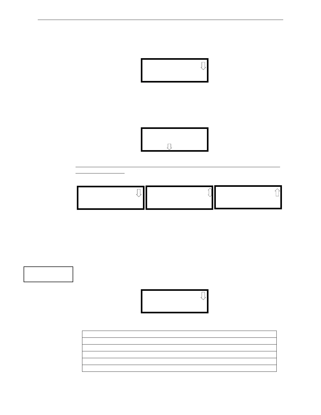
Zones option and display a screen similar to the following:
Pressing the down arrow key will display additional screens for Input Zones 4 through 6. To
program a specific zone, press the number key corresponding to the desired zone while viewing one
of the Input Zone screens.
To program Input Zone 1, press the 1 key while viewing Input Zone Screen #1. The following
screens will be displayed:
To change the programming for the displayed zone, press the keyboard ‘down’ arrow key to view
the Edit Zone screens.
The following examples show the editing of Input Zone 1:
Enable/Disable Zone
To Enable or Disable the zone, press the 1 key while viewing the Edit Input Zone Screen #2. Each
press of the key will toggle the screen between Enabled Yes and Enabled No. If Enabled No is
selected, the zone will be disabled by the control panel, preventing the circuit from reporting alarms
and troubles to the panel. The control panel LCD will display the zone which has been disabled
and FACP will turn on the Trouble indicator.
Type
To select the type of zone being programmed, press the 2 key while viewing the Edit Input Zone
Screen #2. This will cause the control panel to display the following Zone Type Screen:
Pressing the down arrow key displays additional zone types as indicated in the following table.
Zone Type Action When Activated
Pull-Station Fire Alarm
Manual Release
1
Fire Alarm
N/A
Normally Open Contact Fire
N/A
Table 3.1 Zone Types
INPUT ZONES
1=ZONE 1
2=ZONE 2
3=ZONE 3
Input Zone Screen #1
INPUT ZONE 1
NORMAL PULL STATION
PRESS TO EDIT
Edit Input Zone Screen #1
INPUT ZONE 1
1=ENABLED YES
2=TYPE PULL STATION
Edit Input Zone Screen #2
Edit Input Zone Screen #3
INPUT ZONE 1
1=OUTPUT CIRCUIT MAP
2=FREEZE SUPV. YES
Edit Input Zone Screen #4
INPUT ZONE 1
1=ADJECTIVE/NOUN
2=DESCRIPTION
✱✱✱✱✱✱✱✱✱✱✱✱✱✱✱✱
INPUT ZONE
1=ENABLED
2=TYPE
Edit Input Zone Screen #2
ZONE 1 TYPE
1=PULL STATION
2=N/A
3=MANUAL RELEASE
Zone Type Screen #1