28 PDRP-2001 Series Manual — P/N 53043:E4 7/28/2016
Installation Power-limited Wiring Requirements
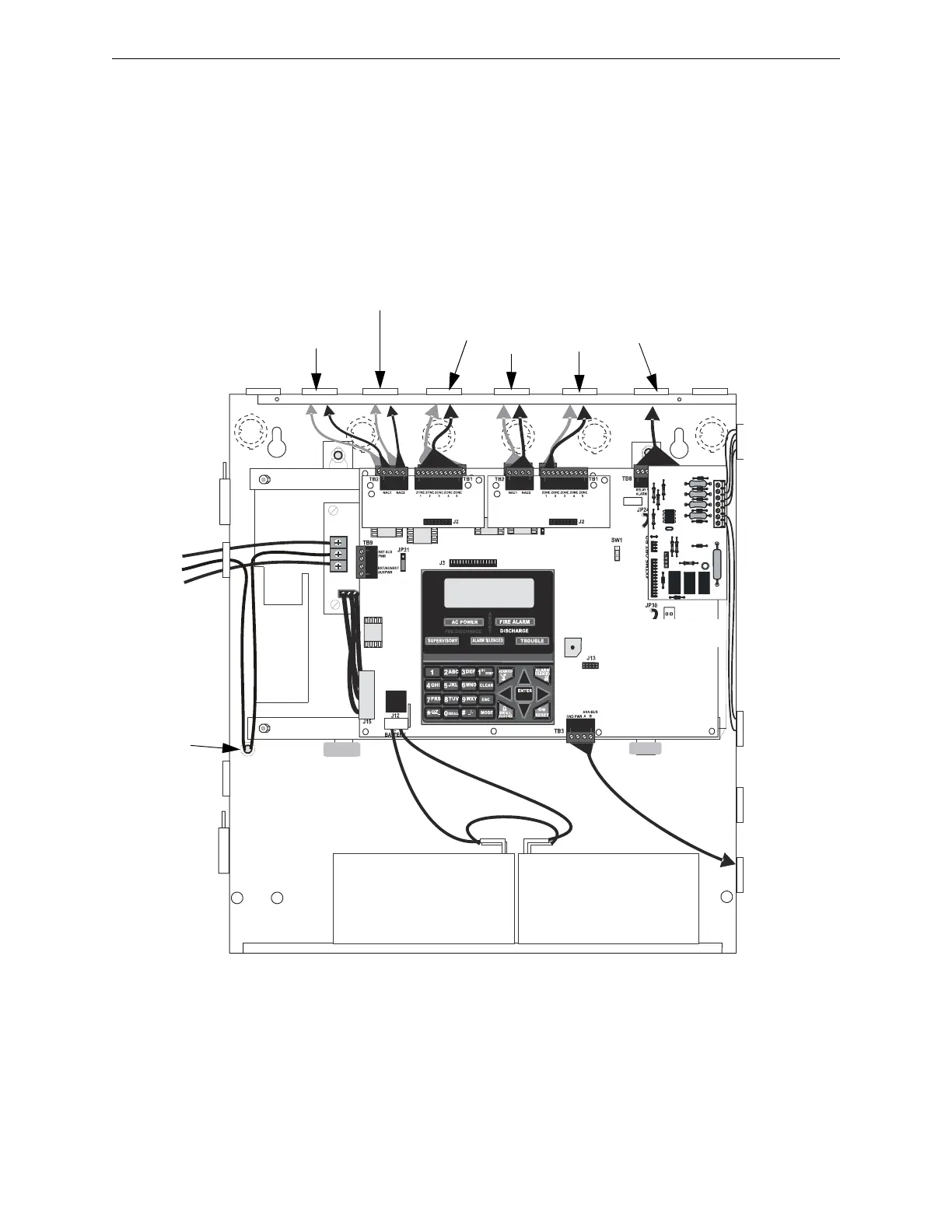
2.5 Power-limited Wiring Requirements
Power-limited and nonpower-limited circuit wiring must remain separated in the cabinet. All
power-limited circuit wiring must remain at least 0.25” (6.35 mm) away from any nonpower-
limited circuit wiring. Furthermore, all power-limited and nonpower-limited circuit wiring must
enter and exit the cabinet through different knockouts and/or conduits. A typical wiring diagram is
illustrated below.
Figure 2.10 Typical UL Power-limited Wiring Requirements
Power-limited Circuits
(Class 2)
Power-limited
Circuits
(Class 2)
Nonpower-
limited
Circuit
AC Power
120 VAC
Hot (L1)
Ground
Neutral (L2)
CAC-5X
RP2001cULwire.wmf
4XTMF
CAC-5X
ground
stud
Power-limited Circuits (Class 2)
Power-limited
Circuit
(Class 2)
Deluge - Preaction Control FACP
Nonpower-limited Circuits*
*Note: In certain applications, an NAC (power-limited circuit) could be adjacent to a
releasing circuit (nonpower-limited without supervision kit REL-4.7K)