44 PDRP-2001 Series Manual — P/N 53043:E4 7/28/2016
Installation ANN-BUS Devices
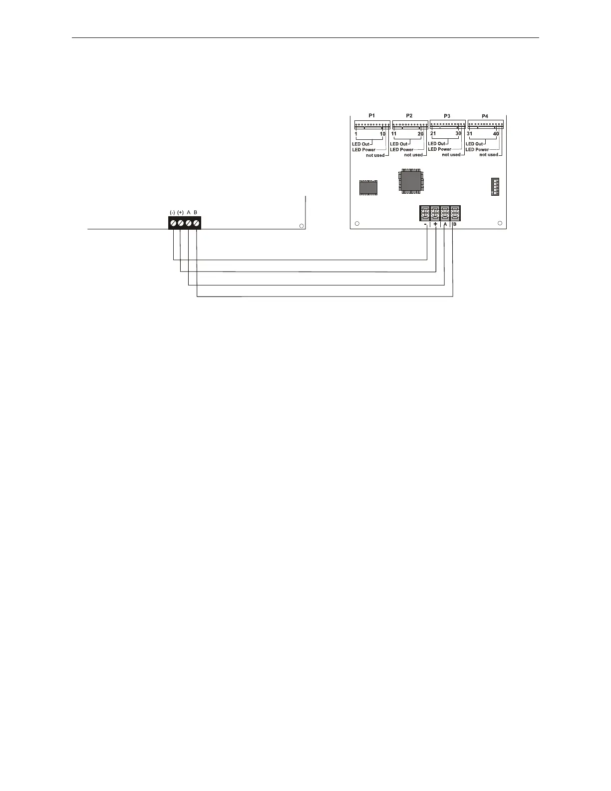
ANN-I/O Connection to FACP
The ANN-I/O connects to the FACP via the ANN-BUS as illustrated in Figure 2.21. After the
ANN-I/O is connected to the panel, it must be added to the system via FACP programming.
ANN-I/O Module LED Wiring
There are four 12-pin connectors on the ANN-I/O module for connecting LEDs. Each set of 10
LEDs get their power from Pin 11 of the corresponding connector. Internal resistors are sized so
that there is approximately 10 mA of current for each LED. No series resistors are required. LED
outputs are mapped to output circuits. Refer to the section titled “ANN-I/O LED Zone
Assignments” on page 68 of this manual.
Figure 2.21 ANN-I/O Connection to FACP
ANN-I/O Module
FACP
ANN-BUS and power wiring are
supervised and power-limited
TB3
ann-IOtorp2001.cdr
Primary ANN-BUS