40 PDRP-2001 Series Manual — P/N 53043:E4 7/28/2016
Installation ANN-BUS Devices
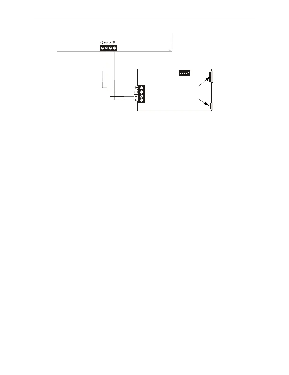
2. Connect the ANN-S/PG to the FACP as illustrated in Figure 2.19
3. Using the DIP switches on the back of the ANN-S/PG module, assign an ID number (address)
to the module
4. Select the address and configuration options for the ANN-S/PG module as described in the
Programming section of this manual (refer to “ANN-BUS” on page 66)
Note that the Auto-configure feature allows the programmer to quickly bring all installed
ANN-BUS modules online (refer to “Auto-Configure” on page 67)
5. Connect a printer to the ANN-S/PG Parallel or Serial connector (refer to Figure 2.19 on page
40)
Specifications
• Operating Voltage: 24 VDC
• Current (Alarm and Standby): 45 mA
• Ambient Temperature: 32
o
F to 120
o
F (0
o
C to 49
o
C)
• Max. Wiring Distance from FACP: 6,000 ft. (1,800 m)
• Mounting: Surface
• Dimensions: 6”W x 7-3/4”H x 1-7/16”D (15.2 cm W x 19.7 cm H x 3.7 cm D)
• For indoor use in a dry location only
PRN-7 Printer Installation
When connected to the FACP via the ANN-S/PG module, the PRN-7 prints the status changes
within the control panel and time-stamps the printout with the time of day and date that the event
occurred. It provides 80 columns of data on standard 9” x 11” tractor-feed paper. This section
contains information on connecting a printer to the control panel and setting the printer options.
Connecting a PRN-7 Printer
Remote printers require a primary AC power source. If required for the fire alarm system
configuration (for example, a Proprietary Fire Alarm System), a remote printer requires a
secondary power source (battery backup). Since a secondary power source is not provided as a
standard feature, a separate UL-listed Uninterruptible Power Supply (UPS) should be used. The
building emergency power supply may be used, as long as it meets the power continuity
requirements of NFPA 72. Refer to NFPA 72 for further details.
Connect the remote printer to the FACP via the ANN-S/PG module using a standard DB-9 cable.
One end of the cable will plug into the DB-9 connector on the PRN-7 printer and the other end
plugs into the serial connector on the ANN-S/PG module.
Figure 2.19 ANN-S/PG Connection to FACP
ANN-S/PG Module
FACP
Cable Connectors for
connection to printer
(Use only one)
Parallel
Serial
ANN-BUS and power wiring are
supervised and power-limited
TB3
annSPGrp2001.cdr
Primary ANN-BUS