English
The water inlets and outlets must be connected as described on the labels afxed near the
connections.
Caution
FILLING OR DRAINING THE WATER CIRCUIT MUST BE PERFORMED BY SKILLED PERSONS USING THE
APPROPRIATE DEVICES ON THE EXTERNAL HYDRAULIC CIRCUIT BY THE INSTALLER.
Caution
VV
VR
VV
VR
UNIT 1
UNIT 2
V : Isolating valves VR : Balancing valves
17SysAqua
When two or three units are connected in parallel, it is recommended that the return circuit connections are
reversed (Tickelman loop system) in order to reduce the pressure loss in each unit’s circuit.
Always check that the manual or automatic air drains are installed at all the high points of the hydraulic
network.
Install a balancing valve on the output pipe to adjust the water ow.
To guarantee proper energy efciency and compliance with current standards, water pipes passing through
uninhabited zones should be properly lagged to retain heat.
To achieve correct insulation with conductivity of 0.04 W/mK, lag the pipes with insulating material with a
radial thickness between 25mm and 30 mm.
10.8. HEAT INSULATION
10.9. FILLING THE SYSTEM WITH WATER
It is important to ensure that the mains water supply pressure is sufcient to ll the installation.
Once the installation is complete and after having clean and rinsed out the circuit network, you must ll
the water circuit in accordance with current professional standards until you obtain the service pressure
which will be:
0.5 bar < Service Pressure < 2.5 bar
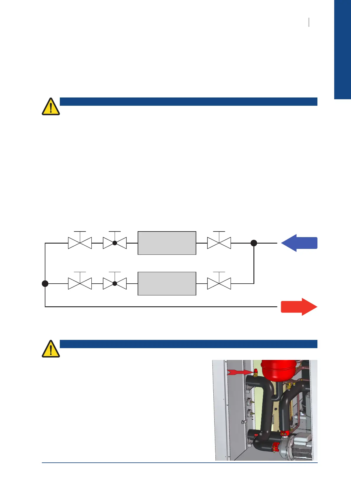
When the hydraulic pump option is selected, a safety valve is
mounted (factory assembled) at the Aqualogic water inlet to
prevent from over pressure in the circuit. The installer has to put
a pipe at the safety valve outlet for water evacuation.
A 3.5 bar safety valve is mounted in the unit when hydraulic options are selected (single or double pump).
 Loading...