English
Access
Services
Commissioning
Status
1/4
Access
Services
Commissioning
Status
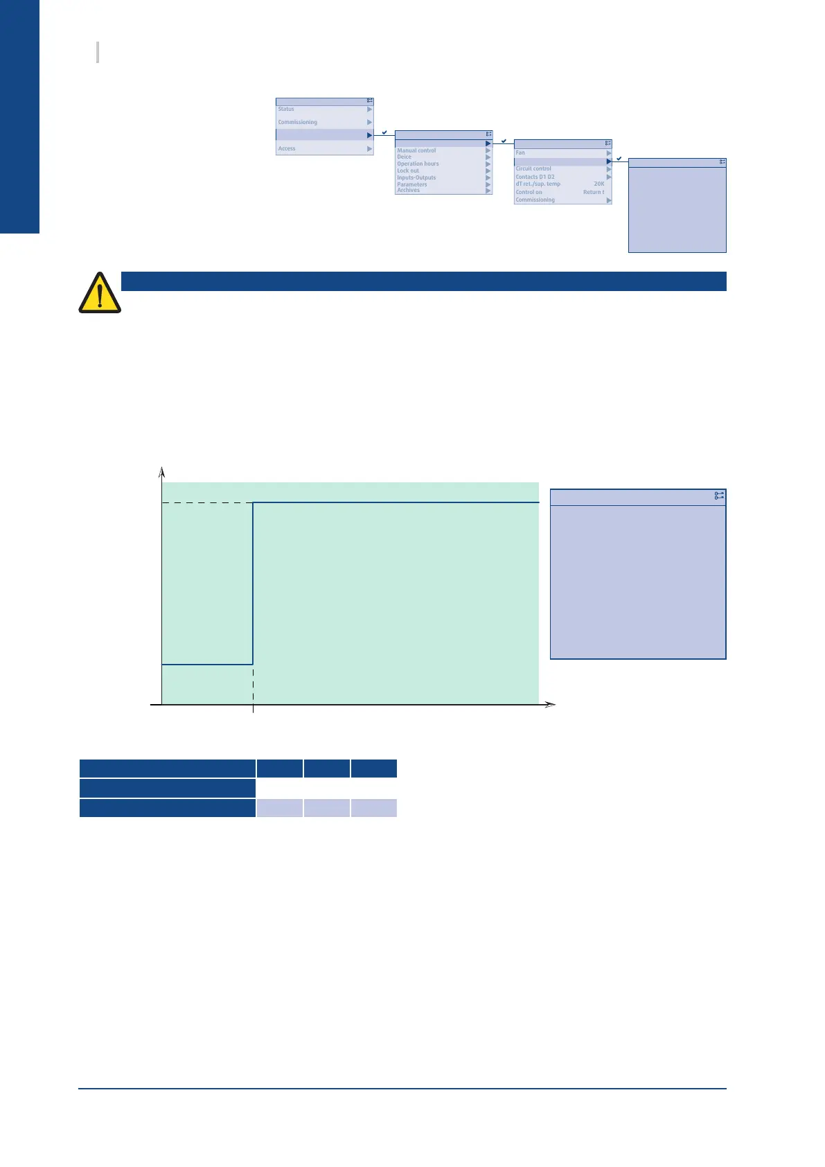
Main Menu
Parameters
Inputs-Outputs
Lock out
Operation hours
Deice
Manual control
Configuration
1/8
Archives
Parameters
Inputs-Outputs
Lock out
Operation hours
Deice
Manual control
Configuration
Service
Control on
dT ret./sup. temp
Contacts D1 D2
Circuit control
Pump
Fan
Configuration
Control on
dT ret./sup. temp
Contacts D1 D2
Circuit control
Pump
Fan
Configuration
1/13
20.0%
40.0%
80.0%
---------------
120s
72h
Active
---------------
2 stages
10 s
Off
Single
Mod. pump standby speed
Mod. pump min speed
Mod. pump max speed
--------------------------
Anti-seizing duration
Anti-seizing frequency
Anti seizing act.
--------------------------
Modulation
Acceleration delay
Continuous pump
Pump
Pump configuration
0%
100%
100%
Step 1
Mod. pump
max speed
Mod. pump
standby speed
The minimum frequency of the pump must not be less than the manufacturer’s recommendations
(e.g. 30Hz) and must ensure a sufcient rate for teh unit (Refer to the § PHYSICAL CHARACTERISTICS,
page 8).
Caution
30 SysAqua
13.4.7. "VARIABLE PRIMARY FLOW” OPTION
The "Variable Primary Flow" option is used to
modulate the power of the hydraulic pump. This modulation is
obtained by powering the pump through a frequency inverter.
13.4.7.1. CONSTANT SPEED MODE
The pump operates at a xed speed whatever the unit capacity. This speed is determined during
commissioning to adjust the power of the pump to the load drops of the installation.
Setting default min max
Mod. pump max speed
100% 0% 100%
Mod. pump standby speed
60% 0% 100%