English
FCU n
FCU 3
FCU 2
FCU 1
WPT
Hz
LWC
PHE
EWC
WP
VE
ACS3
The hydraulic facility must include a system that retains the required minimum water pressure
when the terminals’ two-way valves are shut.
Caution
20.0%
40.0%
80.0%
---------------
120s
72h
Active
---------------
2 stages
10 s
Off
Single
Mod. pump standby speed
Mod. pump min speed
Mod. pump max speed
--------------------------
Anti-seizing duration
Anti-seizing frequency
Anti seizing act.
--------------------------
Modulation
Acceleration delay
Continuous pump
Pump
Pump configuration
1/13
100.0%
20.0%
40.0%
80.0%
---------------
120s
72h
Active
---------------
2 stages
10 s
Off
Single
Capacity for max speed
Mod. pump standby speed
Mod. pump min speed
Mod. pump max speed
--------------------------
Anti-seizing duration
Anti-seizing frequency
Anti seizing act.
--------------------------
Modulation
Acceleration delay
Continuous pump
Pump
Pump configuration
0%
100%
100%
Mod. pump
max speed
Mod. pump
standby speed
Capacity for max speed
Capacity
Mod. pump
min speed
Step 1
31SysAqua
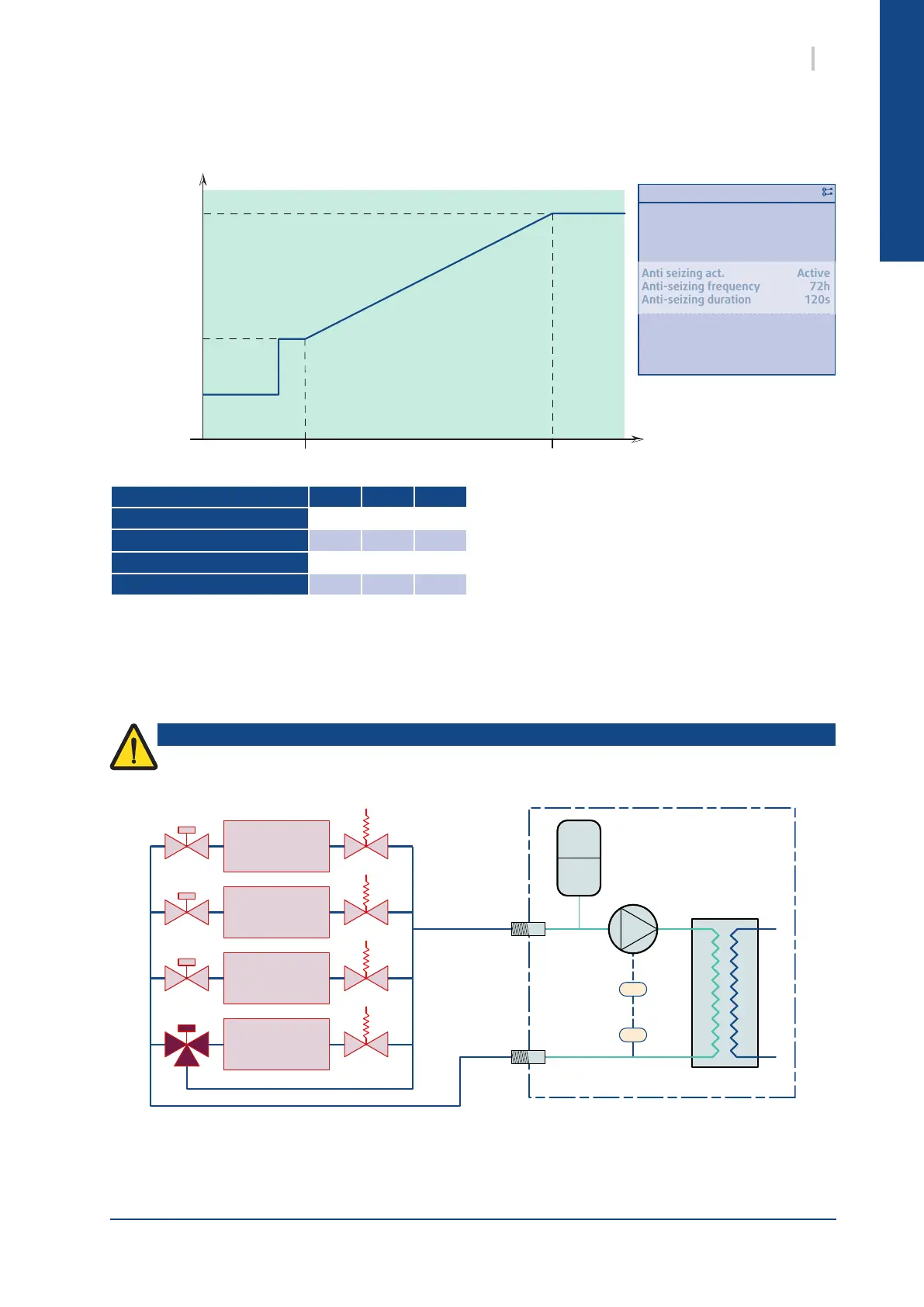
13.4.7.2. CONSTANT SPEED MODE VS CAPACITY
The speed of the pump depends on the capacity of the unit. This speed range is determined during
commissioning to adjust the power of the pump to the load drops of the installation.
13.4.7.3. CONSTANT OUTPUT PRESSURE MODE
The frequency inverter controls the pump’s speed to maintain an even water pressure at the output of the
unit, regardless of the number of operating terminals.
Installation of one or more three-way valves on the facility to maintain the minimum
required pressure.
Setting default min max
Mod. pump max speed
100% 0% 100%
Mod. pump min speed
70% 0% 100%
Mod. pump standby speed
60% 0% 100%
Capacity for max speed
100% 0% 100%