English
The automatic change-over mode is activated if the local mode and the BMS mode are set to
"Auto".
Caution
2xBK
2xBK
2xBK
EWT
LWT
OAT
B1
M
B2
M
T1
B3
T4
D1
M
D2
EEV
T13
COM
COM
B
A
B
A
SD/N
O 1
Information
Selection of the heat/cool mode is only possible in reversible units. This menu does not exist in the
"cool only" versions.
Access
Services
Commissioning
Status
1/4
Access
Services
Commissioning
Status
Main Menu
Parameters
Inputs-Outputs
Lock out
Operation hours
Deice
Manual control
Configuration
Service
1/8
Archives
Parameters
Inputs-Outputs
Lock out
Operation hours
Deice
Manual control
Configuration
Service
1/7
Return t
20K
Commissioning
Control on
dT ret./sup. temp
Contacts D1 D2
Circuit control
Pump
Fan
Configuration
1/7
Return t
20K
Commissioning
Control on
dT ret./sup. temp
Contacts D1 D2
Circuit control
Pump
Fan
Configuration
3/4
Reduced mode
Forced heating
Low shedding
None
Forced heating
NO
Restart required !
After modification of value
Contacts D2
Contacts D1 ON/OFF
2/4
Forced heating
NO
Restart required !
After modification of value
Contacts D2
Contacts D1 ON/OFF
Contacts D1 D2
Access
Services
Commissioning
Status
1/4
Access
Services
Commissioning
Status
Main Menu
1/12
0.0%
0.0%
44°C
44°C
8.0°C
8.0°C
HMI
Schedul.
Automatic
Delegate
Circuit 1
Hydraulic circuit
Capacity
Load
Current setp. heat
Heating setp.
Current setp. cool
Cooling setp.
State from
Mode from
HMI state
HMI mode
Heating
Cooling
Automatic
1/12
0.0%
0.0%
44°C
44°C
8.0°C
8.0°C
HMI
Schedul.
Automatic
Delegate
Circuit 1
Hydraulic circuit
Capacity
Load
Current setp. heat
Heating setp.
Current setp. cool
Cooling setp.
State from
Mode from
HMI state
HMI mode
Status
0.0%
0.0%
44°C
44°C
8.0°C
8.0°C
HMI
Schedul.
Automatic
Delegate
Circuit 1
Hydraulic circuit
Capacity
Load
Current setp. heat
Heating setp.
Current setp. cool
Cooling setp.
State from
Mode from
HMI state
HMI mode
1/12
0.0%
0.0%
44°C
44°C
8.0°C
8.0°C
HMI
Schedul.
Automatic
Delegate
Circuit 1
Hydraulic circuit
Capacity
Load
Current setp. heat
Heating setp.
Current setp. cool
Cooling setp.
State from
Mode from
HMI state
HMI mode
Status
26 SysAqua
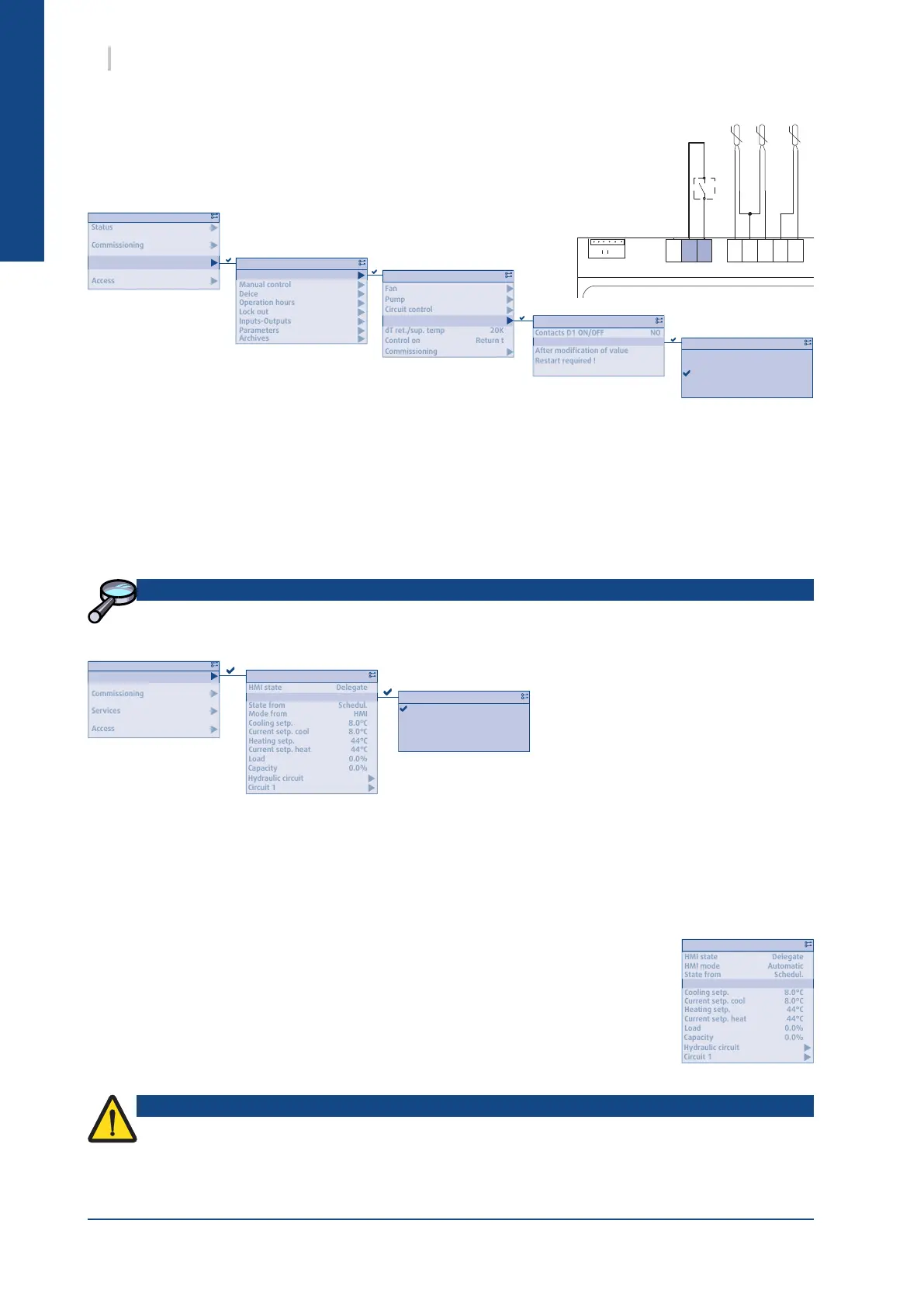
13.4.2. CONFIGURING INPUT D2
During installation, a switch can be connected onto the D2 digital
input.
The operating mode dened for this input takes priority over all control
systems such as the HML, BMS or calendar.
The input can be congured with the
function values dened below:
² None
² Low shedding
² Forced Heating
² Reduced mode
Further information regarding this contact's conguration can be found in thein § CASCADE OF PRIORITIES,
page 26 user manual.
13.4.3. HEAT/COOL SELECTION
The operating mode can be chosen in the "HMI mode" :
² Automatic : delegated to the BMS/Auto-change-over (refer to the UM)
² Cooling : request for cool mode
² Heating : request for heat mode
The "Mode from" line states which element requested the current mode:
² Contact: D2 congurable digital input
² HMI: user interface
² BMS
² Schedul.