English
STARTSTOP
LOC
REM
MENU
ENTER
MENU
EXIT
FWDOUTPUT
Hz
REM
STARTSTOP
LOC
REM
MENU
ENTER
MENU
EXIT
FWDMENU
REM
STARTSTOP
LOC
REM
MENU
ENTER
MENU
EXIT
FWDPAR
REM
STARTSTOP
LOC
REM
MENU
ENTER
MENU
EXIT
FWDPAR
REM
STARTSTOP
LOC
REM
MENU
ENTER
MENU
EXIT
FWDPAR
bar
REM
STARTSTOP
LOC
REM
MENU
ENTER
MENU
EXIT
FWDOUTPUT
Hz
REM
STARTSTOP
LOC
REM
MENU
ENTER
MENU
EXIT
FWDMENU
REM
STARTSTOP
LOC
REM
MENU
ENTER
MENU
EXIT
FWDMENU
REM
STARTSTOP
LOC
REM
MENU
ENTER
MENU
EXIT
FWDMENU
REM
STARTSTOP
LOC
REM
MENU
ENTER
MENU
EXIT
FWDMENU
REM
STARTSTOP
LOC
REM
MENU
ENTER
MENU
EXIT
FWDMENU
REM
STARTSTOP
LOC
REM
MENU
ENTER
MENU
EXIT
FWDMENU
REM
STARTSTOP
LOC
REM
MENU
ENTER
MENU
EXIT
FWDMENU
REM
STARTSTOP
LOC
REM
MENU
ENTER
MENU
EXIT
FWDMENU
REM
STARTSTOP
LOC
REM
MENU
ENTER
MENU
EXIT
FWDMENU
REM
STARTSTOP
LOC
REM
MENU
ENTER
MENU
EXIT
FWDMENU
REM
STARTSTOP
LOC
REM
MENU
ENTER
MENU
EXIT
FWDSETPAR
bar
REM
STARTSTOP
LOC
REM
MENU
ENTER
MENU
EXIT
FWDMENU
REM
STARTSTOP
LOC
REM
MENU
ENTER
MENU
EXIT
FWDSETPAR
bar
REM
STARTSTOP
LOC
REM
MENU
ENTER
MENU
EXIT
FWDSETPAR
bar
REM
STARTSTOP
LOC
REM
MENU
ENTER
MENU
EXIT
FWDOUTPUT
Hz
REM
32 SysAqua
The frequency inverter ACS3 displays the reading via the pressure transducer WPT.
1. Set all units in demand to open all the valves (load = 100%).
2. Check that the output is in line with SysAqua requirements.
3. Read the pressure value from the transducer (example: 4.0 bar).
It is necessary to determine the pressure setting to be maintained in the system then set the frequency
inverter according to this pressure value.
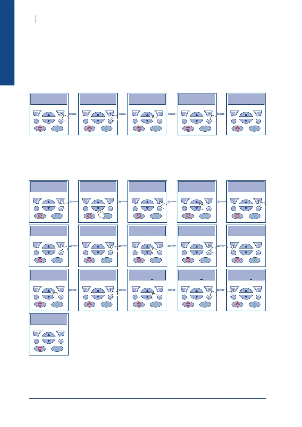
13.4.7.3.1. DETERMINATION OF THE PRESSURE SETTING
13.4.7.3.2. SETTING THE PRESSURE SETTING
The pressure setting is set in two stages:
1. Access parameter 4006 and set it to 22 to display units in bar.
2. Access parameter 4011 then set the required pressure setting (example 4.0 bar).
When the pressure setting is set, check that the system is operational in the following conditions:
² when in partial load, the pressure is constant.
² when at zero load (all units off), check that the inverter frequency has dropped to the minimum
value and that no water pressure alarm is triggered
 Loading...