English
Before connecting the supply lines, check that the voltage available is within the limits specied
(Refer to the § ELECTRIC SPECIFICATIONS, page 10).
Caution
Supplying the unit with a line with an unbalance exceeding the acceptable value results in
cancelling the warranty.
Caution
Correction of the excessive centralized power factor (>0.95) may generate transient phenomena
dangerous for the motors and contactors of the unit during the start and stop phases. Check
instant voltages during these phases.
Caution
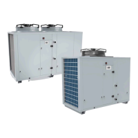
KA1
20 SysAqua
VERY IMPORTANT:
3N~400V-50HZ
The outdoor unit is equipped as standard with a phase sequence
and cut-out controller located in the electrical box.
THE LED’s INDICATE THE FOLLOWING CONDITIONS:
Green LED = 1
Yellow LED =1
Power ON
The compressor rotation
direction is correct.
Green LED = 1
Yellow LED =0
Phase inversion or phase
absent (L1)
The compressor and the fans
do not start.
Green LED = 0
Yellow LED =0
Phase absent (L2 or L3)
The compressor and the fans
do not start.
Voltage differences between each phase do not have to exceed 2 %.
If the unbalance is inacceptable, call the distribution company to have this anomaly corrected.
These units are equipped with a local switch used as general terminal board.
 Loading...