_________________________________________________________________________________________________________
VR 250 ECH/B Installation description
206609 (17-09-2010)
13 Systemair AB
GB
Before starting the system
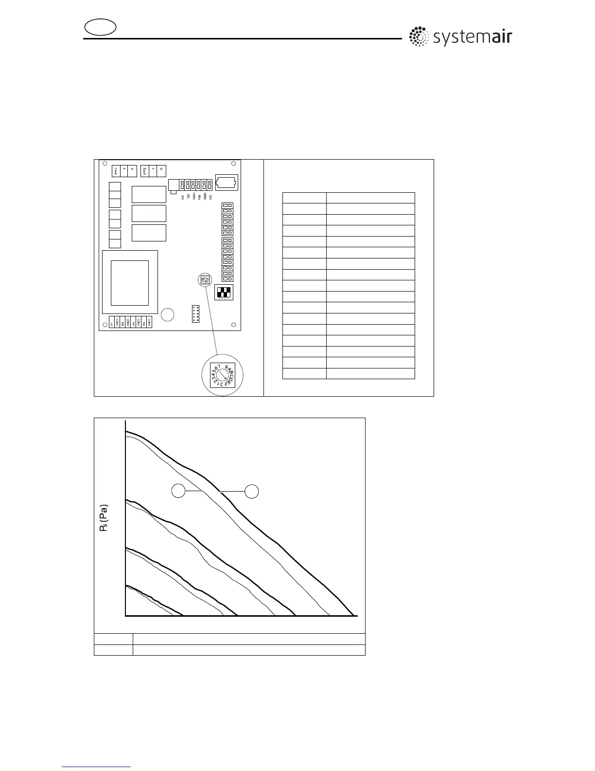
1. Choose required airflow at normal fan speed as follows:
Set the normal fan speed from a potentiometer on the print card in the unit (see fig. 13). The
potentiometer is set by using a screw driver. Each setting corresponds to a different fan speed based
on certain voltage output to the fans (see table 1). To get an idea of the airflow corresponding to each
setting see fig. 14 showing a fan performance diagram displaying performance curves for supply air
and extract air.
DI1
Lo
Hi
GND
12V
AI2
GND
AI3
GND
AI4
GND
GND
AI1
R
N
Earth
R
N
R
N
DI2
220V Aux 2 220V Aux 1
COM
8
8
Table 1
Setting Voltage output (V)
0 3,63
1 3,99
2 4,35
3 4,72
4 5,09
5 5,45
6 5,82
7 6,17
8 6,54
9 6,9
A 7,27
B 7,64
C 8,00
D 8,36
E 8,73 (Default)
F 10,17
Fig. 13
0
5
10
15
20 25 30 35
40
45 50 55
50
100
150
200
0
250
300
350
400
Q(l/s)
4.1V
6V
1
2
7.7V
10V
1 Fan performance curve extract air
2 Fan performance curve supply air
2. Adjust diffusers and louvers in accordance with commissioning or basic setting (see
"Diffusers/Louvers"). Make sure that the inlet diffusers are set so that the air stream is not lead
towards visible joist, wall etc. close to the diffuser.