Nano ITC Getting Started Guide Page 13
reference cells. A proportional/integral/derivative (PID) control loop uses a control heater on the sample
cell to maintain a zero temperature difference between the sample and reference cells. The power required
to maintain this zero difference is used as the calorimeter signal and is monitored as a function of time. If a
reaction that produces heat occurs in the sample cell, the heat required to maintain the zero difference
decreases by the amount of heat supplied by the reaction, resulting in a peak in the thermogram.
A calibration heater located on the outside of the sample cell is used to provide precisely controlled heat
pulses for electrical calibrations, and to verify instrument performance.
The entire measuring unit is encased within an insulated air-tight canister which has been purged on a vac-
uum pump and filled with dry nitrogen at the factory. This is to prevent possible condensation and
evaporation of moisture around the unit which would create excessive baseline noise.
CAUTION: The purge port valve on the back of the Nano ITC should remain in the closed posi-
tion at all times to maintain the integrity of the nitrogen purge.
NOTE: Purging of the canister is not a routine maintenance operation; contact TA Instruments before
proceeding.
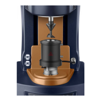
Reaction Vessel
The calorimeter uses two matched reaction vessels with options of 1-mL gold, 190-µL gold, or
1-mL Hastelloy
®
. The vessels are accessed through platinum tubes. The reference cell is constructed to
match as closely as possible the thermal properties of the sample cell. Accordingly, a reference needle is
placed inside the reference cell during operation to correspond to the titrant needle in the sample cell.
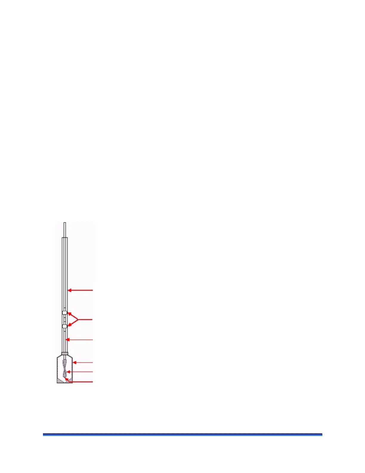
Figure 5 Sample cell assembly.
CAUTION: Extreme care should be taken not to bend the syringe needle, because this would
impair proper stirring and possibly damage the reaction vessel.
Platinum
Access Tube
Teflon Bushings on
Needle to Dampen
Stirring Noise
24K Gold
Reaction Vessel
Titrant Delivery
Needle
Stir Paddle
Titrant Exit Point
 Loading...