the down current source. The trigger current source is
comprised of the Q8 and R19.
6-3-2. Voltage Controlled Oscillator
Figure 6-3 is a simplified block diagram of the VCO sec-
tion. Refer to this Figure throughout the following de-
scriptions. Assuming that the diode bridge switch is oper-
ating in such a way that I up is flowing to the range capaci-
tor, the capacitor is charged with this current which creates
a positive going voltage ramp. This voltage ramp is fed
through an impedance converter to the triangle buffer.
This buffer isolates the capacitors from the level detector
and provides sufficient voltage amplitude for the level de-
tector. When the voltage ramp reaches a predetermined
threshold level, the level detector operates the diode
switch so that the current now flows through the I down
source. This causes the same reaction as described above
but with opposite direction. The following paragraphs de-
scribe the voltage controlled oscillator in depth.
DIODE SWITCH - The diode switch consists on the fol-
lowing parts: CR19, CR20, CR17, CR18, CR21 and
CR22. The up current is supplied through R67 and the
down current is supplied through R68. CR17 and CR19 as
well as CR18 and CR20 are connected in series to reduce
the feedthrough from the switch drive signal to the range
capacitors.
TRIANGLE BUFFER - The triangle buffer includes im-
pedance converter FET Q19, transistors Q22, 23, 24 and
Q25 and their associated components.
LEVEL DETECTOR - The level detector consists of
U43 and Q27 through Q30. The positive threshold is set by
R101 and R107 and the negative threshold is set by R104
and R106. The rectangular signals which are then used to
switch the diode switch are taken from Q27 and Q30. Q26
with CR23, CR24 and CR25 translate the rectangular
waveform from the collector of Q28 to a TTL level signal
which is then sent to the trigger circuitry.
RANGE CAPACITORS - The frequency at the main out-
put is being generated by charging capacitors which also
create the triangle waveform. The range capacitors C38
through C46 are used for the 20Hz to 20MHz ranges. U38
receives the serial data from the digital circuit, converts
the serial data to parallel information which is fed to the
quad comparator U39. The outputs of the quad compara-
tor are then fed to the bases Q15 through Q18 which in turn
select the correct range capacitor.
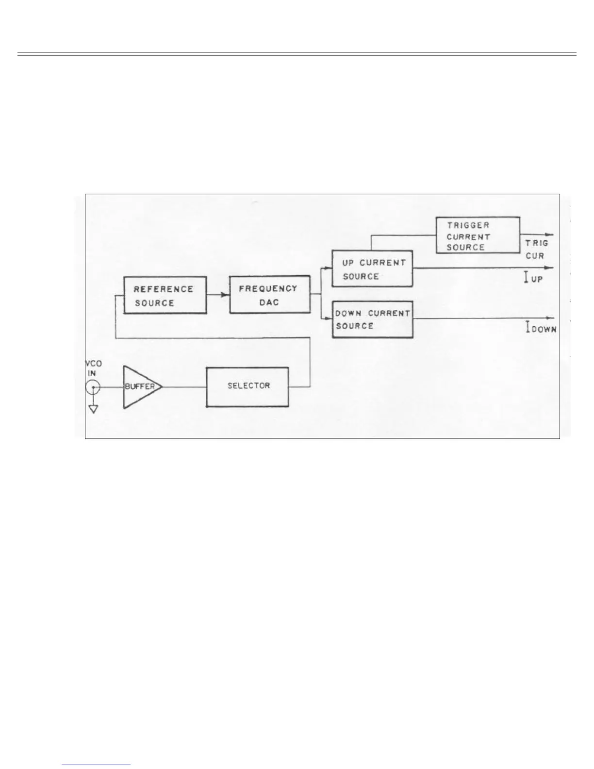
Figure 6-2. Current Generator Simplified Block Diagram
Model 8020 Theory Of Operation
Page 6-3