clamps the input of the triangle buffer to a level which is set
by the clamp voltage generator.
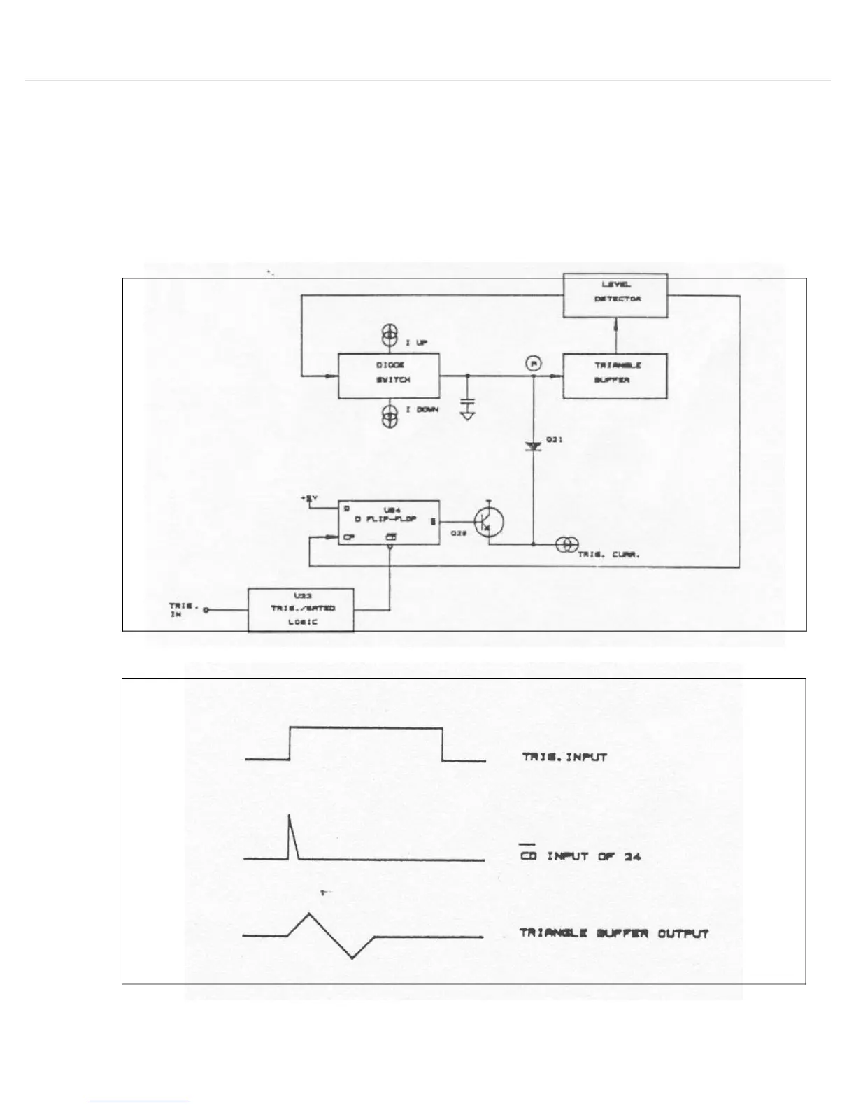
Figure 6-5 shows the waveforms of the clamp circuit in
triggered operating mode and Figure 6-6 shows the wave-
forms of the clamp circuit in gated operating mode.
TRIGGER LOGIC - The trigger logic is formed by U22
and U24. The triggering signal is routed through R12 to the
input of U22A. Selecting continuous mode sets the con-
trol inputs of U22b and U22c to “0". This sets U24 to ”0"
level and keeps Q21 off. This action blocks any signals
coming from the trigger input.
Figure 6-4. Model 8020 Clamp Circuit Simplified Diagram
Figure 6-5. Model 8020 Clamp Circuit Waveforms (Triggered Mode)
Model 8020 Theory Of Operation
Page 6-5