When the generator is set to operate in Gated mode the
gating signal is routed through U22 to U24. The VCO is
enabled when the gating signal is high and disabled when
the gating signal is low.
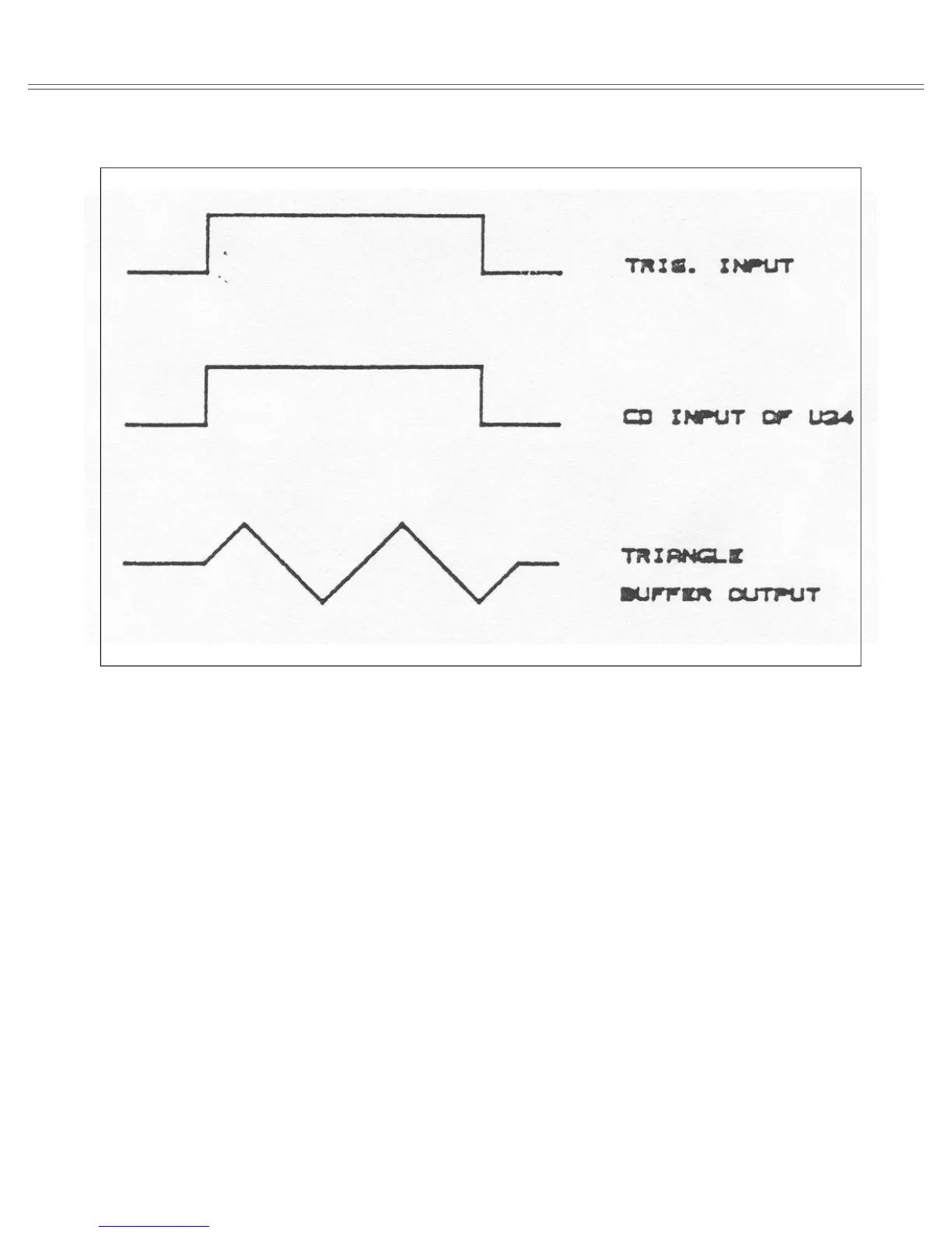
Selecting triggered mode, sets the controlling input to
U22B to high and the controlling input to U22C to low. A
positive transition from the trigger input generates a nar-
row negative going pulse at U24. This sequence in turn
enables one cycle at the VCO output.
6-3-5. Pulse Shaper
The purpose of the pulse shaper is to convert the signal
from the level detector to pulses having very fast rise and
fall times and with precise amplitude. The pulse shaper is
located on the output amplifier assembly board. Refer to
the schematics at the end of this manual throughout the
following description.
The pulse from the VCO is routed via U1 to the pulse
shaper. The pulse shaper consists of Q1, Q2, Q3 and Q4,
positive current generator Q10 and negative current gen-
erator Q9. When the generator is set to operate in square-
wave function, the output of the pulse shaper, alternates
between the positive current source and the negative cur-
rent source. When in positive pulse function, the output
alternates between the positive current source and ground
and when in negative pulse function, the output alternates
between the negative current source and ground. The
positive current source consists of U3, Q10 and their asso-
ciated components. R127 adjusts the positive current. Q7
controls Q8 when positive pulse is selected. The negative
Current source consists of U2, Q9 and their associated
components. R126 adjusts the negative current ampli-
tude. Q5 controls Q6 when negative pulse is selected.
6-3-6. Preamplifier
The pre-amplifier is located on the output amplifier as-
sembly board. Refer to the schematics at the end of this
manual throughout the following description. The pream-
plifier consists of U11, Q12, Q13, Q14, Q15 and Q16 and
their associated components. U8 is a serial to parallel con-
Figure 6-6. Model 8020 Clamp Circuit Waveforms (Gated Mode)
Theory Of Operation Model 8020
Page 6-6